- Home Old school pinball <1985
- Grand Prix (EM) 1976
- Firepower (SS) 1980
- Space Mission (EM)1976
- Genie (SS) 1979
- Magic Castle (SS) 1984
- Black Knight (SS) 1980 New school pinball >1985
- High Speed (Sys11) 1986
- Earthshaker (Sys11) 1989
- CFTBL (WPC) 1992 Arcade Project
- JK-Cabinet with MAME Contents Grand Prix
- Playfield Cleaning - Part 1
- Playfield Cleaning - Part 2
- Cabinet Refurbishing
- Backbox Refurbishing
- Troubelshooting
- Finsihed project
- Documents - Flyer
|
Languages |
|
|
WMS Grand Prix EM Cabinet Refurbishing - Part III!
MECHANISM PANEL AND SCORE MOTOR
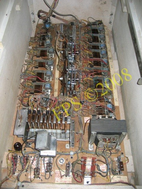
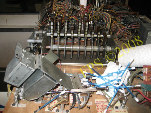
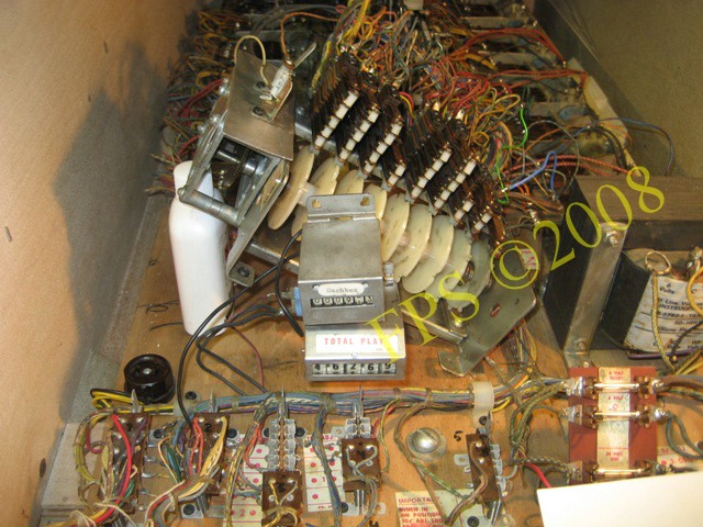
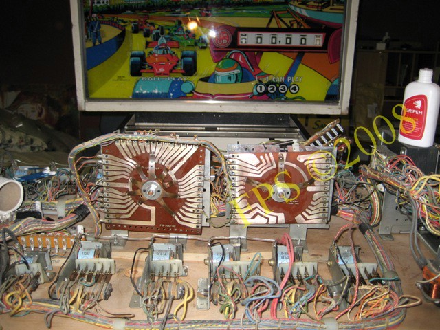
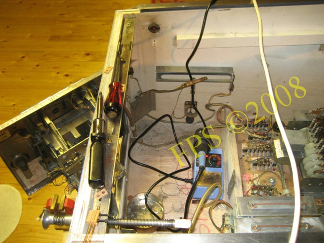
In the picture above the complete mechanism panel including transformer, Jacks, relays, Score motor, Stepper units, Spinner unit which is situated in the bottom of the cabinet. In the front end we can se the holder for fuses.
SCORE MOTOR
 |
 |
 |
 |
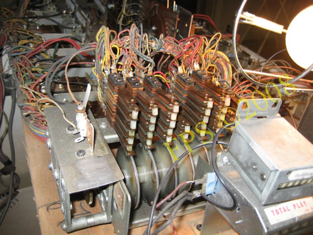
The pictures show the Score motor for Williams Grand Prix. Notice all dirt and carbon dust on and around the score motor, also how much oil there was on the switches, it is very important that these switches is absolutely clean and correct adjusted to assure the function of the pinball.
The score motor is the pinball's heart - it controls almost all functions in a electromechanical pinball. It consists of a electrical motor, axle with notched cams which activates the switches while the axle turns by the motor. The switches is open and closing while the cams is turning.
For example if 5.000 points is scored by hitting a target on the playfield a signal is given by a relay to start the score motor - the score motor makes 5 turns and activate a switch each turn which make a signal to another relay and the score wheel score points - then another switch turn the relay off - simply described.
To mention is that a index cam keep control of the score motors zero/home position.
WARNING- be careful when cleaning and adjust the switches since it is easy to make wrong adjustments or bend a switch during cleaning, continuously use the electrical schematic as reference during the work. During my work with the score motor the classic brain ghost appear and I started to be doubtful about what I had done or not had done during the cleaning/adjustments.
Many problems with older electromechanical pinball's can be related to a dirty or misadjusted score motor. In my case the only thing that happened when the start button was pressed was that the score motor rotated 1/4 turn.
TOTAL REVIEW and COMPLETE CLEANING REQUIRED...
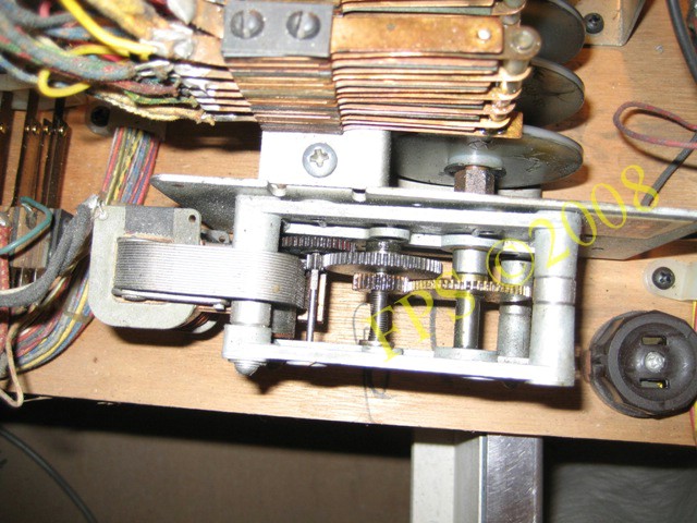
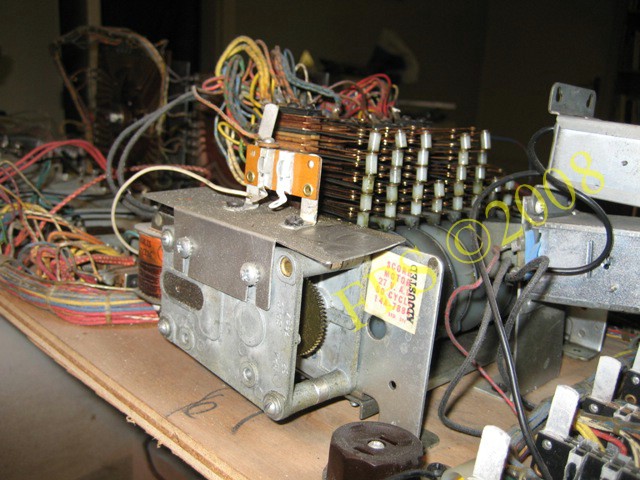
Underneath the cover is the electrical motor and cogs who drive the axle with notched cams, time to clean and lubricate the cogs with Super Lube.
 |
 |
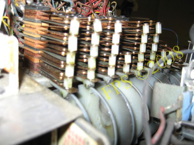
Here I work with the cleaning of score motor switches, a lot of q-tips soaked in Acetone where used since some of the contact blades was lubricated with a lot of oil.NO LUBRICATION OF SWITCHES ALLOWED.
 |
 |
It is possible to manually turn the score motor by using a small spanner to see how the switches open and close, if the two screws is removed on the left end of the score motor it is possible to rise it up and make it easier during the work with the motor.
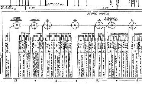
To verify that all switches was correct adjusted "Normally Open" (N.O) and "Normally Closed" (N.C) I made a matrix in excel based on the electrical schema to make it easier to verify each switch. The matrix was also useful when I followed a wire from a switch on the score motor during error seek. The matrix describe each cam with switches in letter order with A closet to the cam, also the wire color code for each switch is in the matrix.
R-W-3 = three wires with color code Red-White. There is a type of switches which consists of both N.C and N.O and they are called Make and Brake M&B. To see the matrix open the picture above.
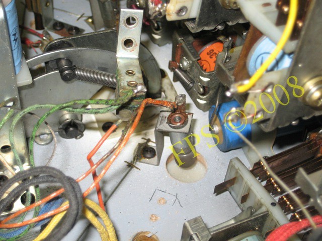
I found a wire where the isolation had melt - probably due to a short cut - which I replaced and one wire which was loose. The contact point where to solder the loose wire I had to trace by the wires color code on the isolation and the electrical schematic.

Now is all switches and the score motor cleaned.
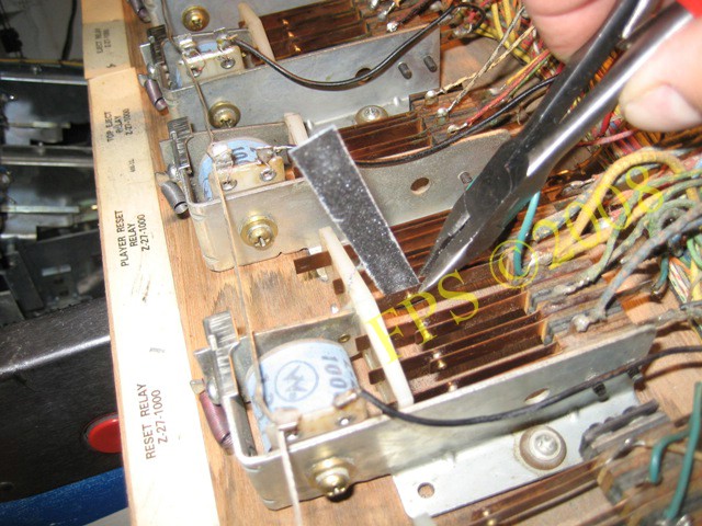
ADJUSTMENT AND CLEANING OF RELAYS
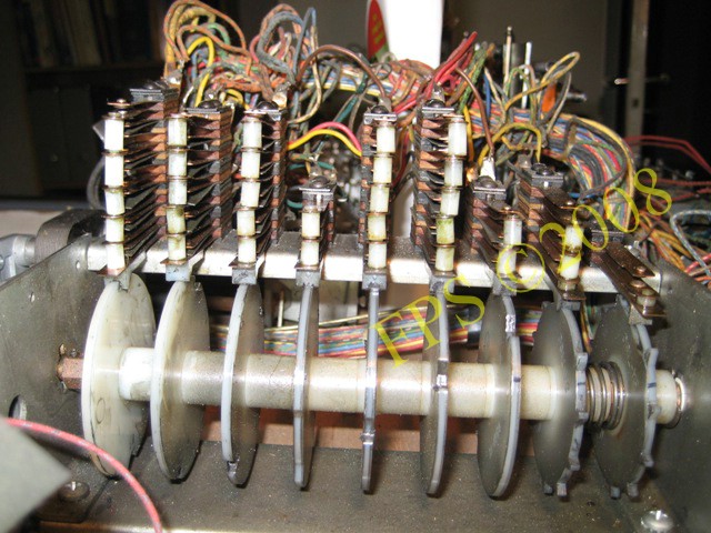
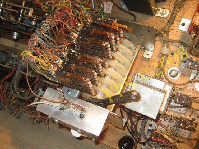
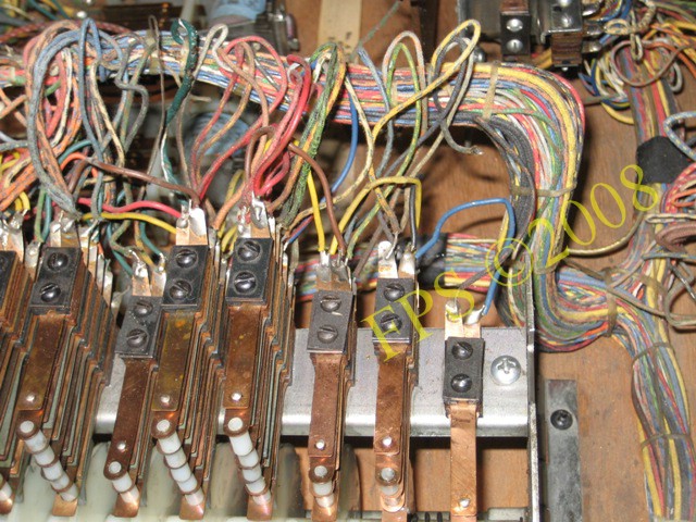
The picture show the mechanism panel in the bottom of the cabinet with relays and other units. A relay consist of one or more switch leafs and a "sledge" which moves when activated by the solenoid, electromagnet. There is often both normally open (N.O) and normally closed (N.C) switches in one relay and almost for all functions in a electromechanical pinball a relay is involved. It is important that the switch leafs contact points is clean and correct adjusted according to the pinball's manual. Every relay is described in the manual with color code for wires, the position for the switch (N.O/N.C) also where the signal from the switch is addressed. I use the manual and verify that correct wire is soldered to every switch in the relays and pull gently in the wire to se if the solder point is still strong.
If the switch leafs contact points is corroded with carbon dust I sand with a sand paper of fine grit or use a "Flexstone" file. I move the Flexstone file between the contact points and squeeze them gently with a mini long nose pliers during the process. Afterwards I clean with a q-tip soaked in Acetone.
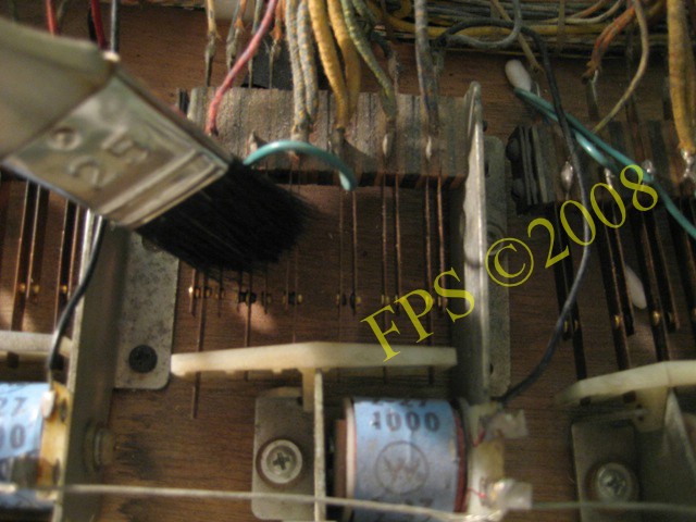
With a brush I remove dust and remainder from sanding of the contact points if hard to get with a q-tip.

Now is the switch leafs contact point shiny clean and make good contact.
 |
 |
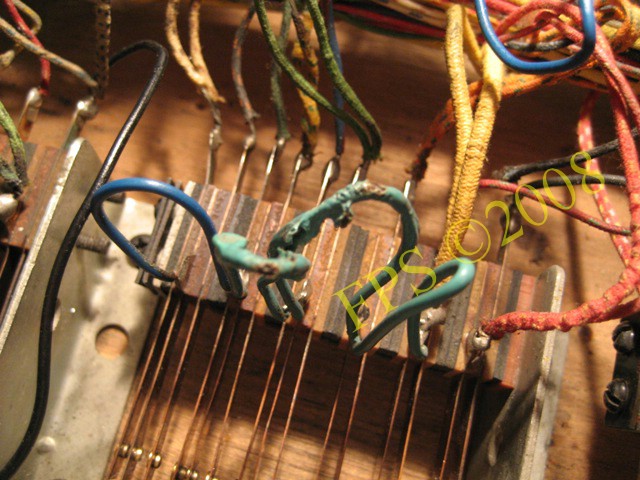
It is common that there are broken wires and that the wires isolation has melted due to short cuts. I replace them. The electromechanically pinball's wires has an isolation of fabric but sometimes wires with isolation of plastic can be found and I do not know if these are new replacement wires or original wires?
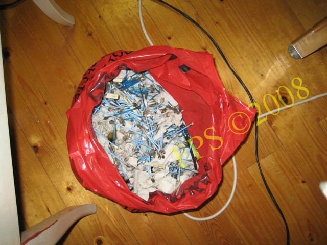
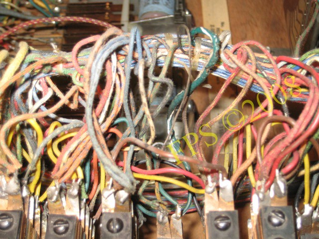
In the picture we can see evidence of how dirty the relays in the Grand Prix and was in need of cleaning - I needed to clean then several times to get them absolute clean.
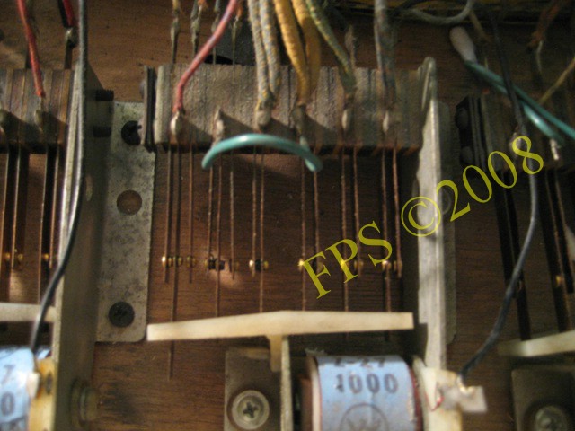
Two stepper units backlit disks and finger wipers cleaned.
A lot of dirt was on the lamps. All lamps was replaced from #44 to #47 which consume less current and therefore develop less heat. The backside of inserts on the playfield was cleaned with Novus 2.
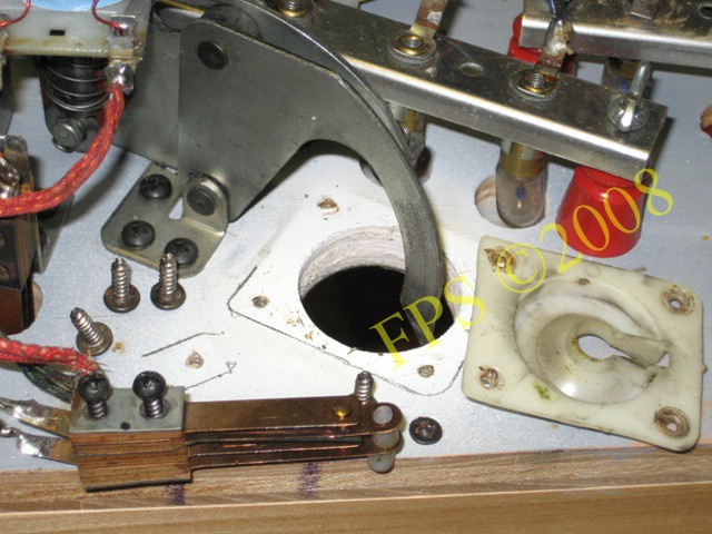
Here we can see cleaning of switch for kick out hole and the eject shield plastic.
FLIPPER SWITCHES
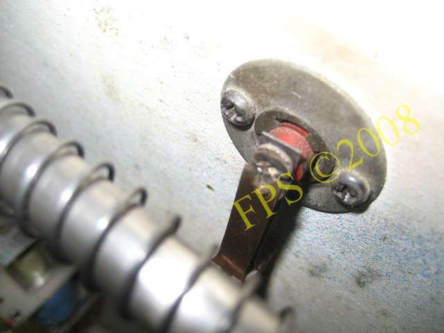
The flipper switches on the inside of the cabinet was substantial frayed and needed to be changed on both sides. When the flipper was activated during play the flipper bate was hanged in the upper position since the contact points was frayed and burn together. The contact points in these switches consist of heavy stone and can be polished with a small steel file to remove oxidation, but it did not help in my case.
Here, I change they old flipper switches against new switches. Important is to get same distance between the switch leaf blades and distance between the switch itself and the flipper button in the wall of the cabinet as the original switch. It is little trimming with the switches backlit disks to achieve the distance since the switch is compressed when the screws I tighten to the cabinet and the distance change. The backlit disks has different thickness so the distance can be changed by replacing and moving the disks.
Pleasure and Pinball
© FPS. All right reserved. |
Page Last updated:
2008-08-15 |