- Home Old school pinball<1985
- Grand Prix (EM) 1976
- Firepower (SS) 1980
- Space Mission (EM)1976
- Genie (SS) 1979
- Magic Castle (SS) 1984
- Black Knight (SS) 1980 New school pinball >1985
- High Speed (Sys11) 1986
- Earthshaker (Sys11) 1989
- CFTBL (WPC) 1992 Arcade Project
- JK-Cabinet with MAME Contents Magic Castle
- Playfield Refurbishing
- Backbox Refurbishing
- Cabinet Refurbishing
- Electronics
- Refurbishing Diary
- Finished project
- Dokument - Flyer
|
Language |
|
|
Zaccaria Magic Castle Refurbishing project - Part IV!
MAGIC CASTLE (SS) 1984 - ELECTRONICS
My Zaccaria Magic Castle in 1984 did not work except for general illumination on the board and in the backbox. The first thing I checked in the machine was all the fuses, not blown and had the correct amps value, these are placed on the power board and at the voltage transformer in the cabinet, there are also two fuses on the underside of the playfield. It is important to verify that the fuses has the correct value since there are plenty of crazy people who inserting a fuse with a higher value than what the label says just because the fuse before blow due to an unknown problem. For example, you can find a 30A fuse when the label says 5A or something as brutal as a nail or a screw.
FUSES
Cabinet:
Backbox - (Power supply board):
Underside of playfield:
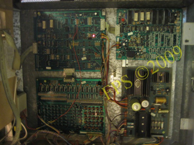
POWER SUPPLY

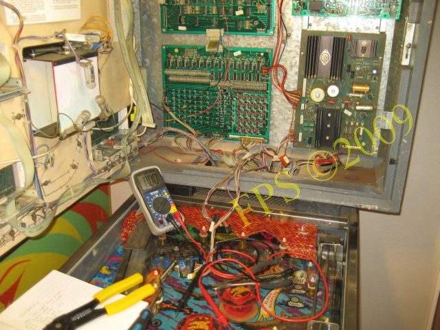
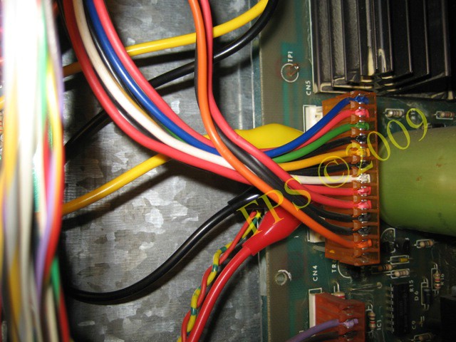
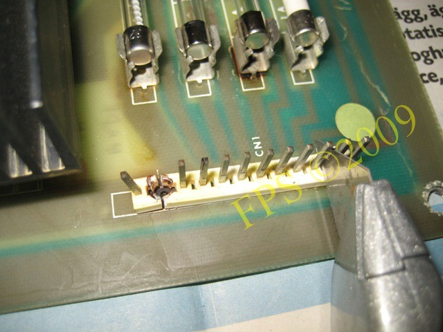
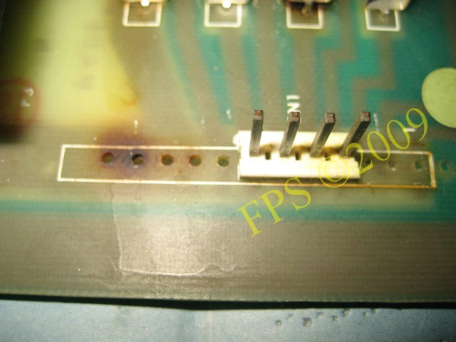
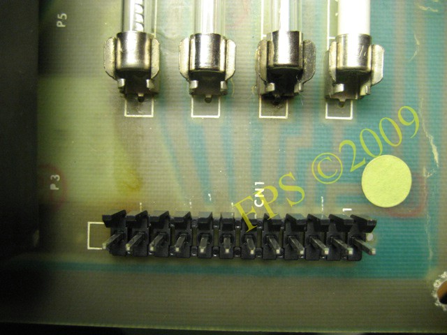
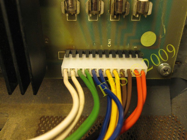
An important aspect to check is that the power board get the correct voltage from the transformer and it is done at CN1 connector on the power board. But as we see in the picture above CN1 has been destroyed by overheating at some point in time. Instead of replacing the CN1 connector the wires where soldered directly to the back of the power board.
Below are my results from measurements of the incoming voltage to the power board. Voltage is measured in parallel on a circuit and in this case we measure the colour pair of wires. In order to perform this measurement we first disconnect all other connectors from the power board.
Wire color - Default value - Measured value
With these results, I can assume that the power board get correct voltage input from the transformer.
POWER SUPPLY BOARD
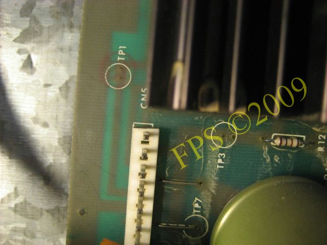
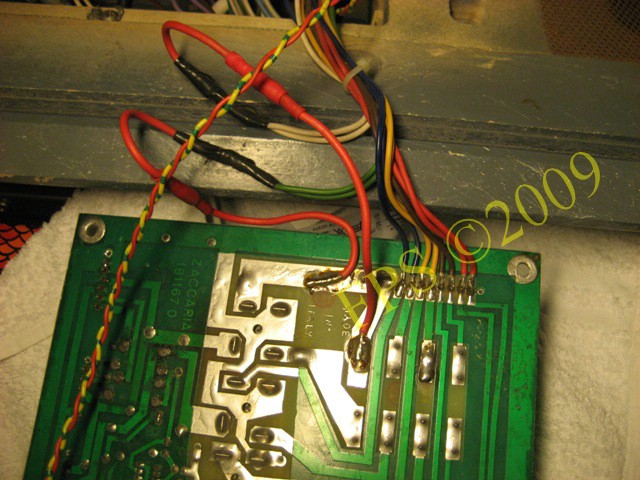
To check the voltage on the power board, there are several test points that can be measured with a multimeter. On my power board the test points wire loops was missing where to connect the multimeters probes. This can be fixed by making their own wire loops by a piece of thin copper wire.
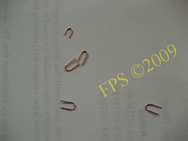
I use copper strands from a cable 1 mm2 and bent them into small loops which I then could attach to the test points holes in the board and fixed them on the boards backside with solder.
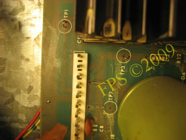
Here we see test point TP1, TP2 with "loops" ready to be measured with a multimeter.
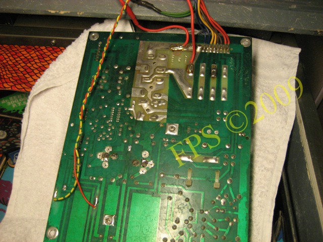
The power board has seven test points which can be measured with a multimeter, VCD. Put the multimeters black probe on TP8 and use the red probe to measure these test points TP1-TP6. TP7 is checked with a logic probe, connect black alligator clip (ground) to TP8 and use the probe tip to check TP7. No signal read from the probe all is OK. If TP7 logic is bad the probe´s green LED is lit (low signal) and indicate that there can be something wrong with the voltage monitor circuit even if TP1-TP6 is measured as OK.
TPx = Default value - Measured value
The measured voltages for TP1, TP2 differs from default value but is nothing that affects the function of voltage supply to the other cards, the board seems to supply properly voltage at this measurement. If any of these test points showing 0-1 VCD this suggests that one of the three rectifier bridges are broken and need to be replaced.
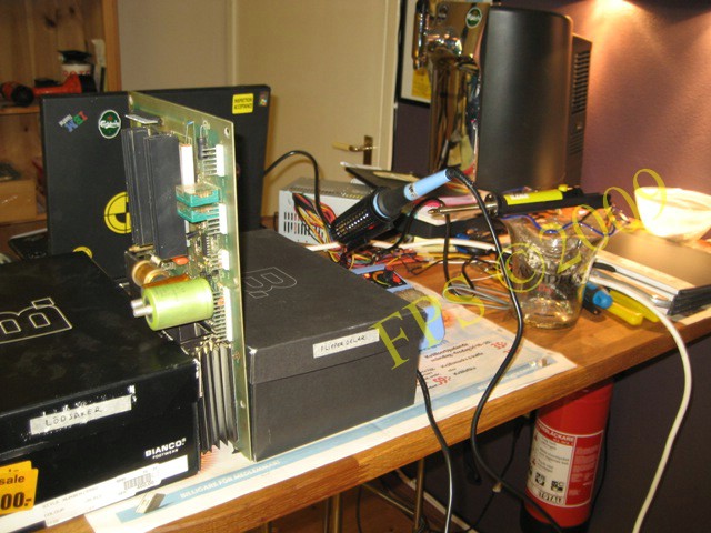
CPU BOARD ON THE BENCH
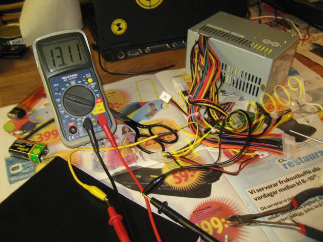
To test the CPU board outside the pinball machine I use a transformer from a computer. We need +5 VDC, +12 VCD and -12 VCD outputs from the transformer, then we can use it to bring power to most CPU / MPU boards for pinball. In my case I got hold of a cheap used but functioning transformer with the desired outputs. Most transformers to computers has outputs +5 VCD (red cable) and +12 VCD (yellow cable) to drive such as a floppy or CD-ROM. To obtain the transformer to start you need to "cheat" it to believe that it is the connected to a motherboard in a computer, this is done by bridging the green wire and black ground wire on the connector used for the motherboard. -12 VCD (blue cable) is found on the connector used for the motherboard, wire colour may vary from transformer to transformer but should follow some sort of standard.
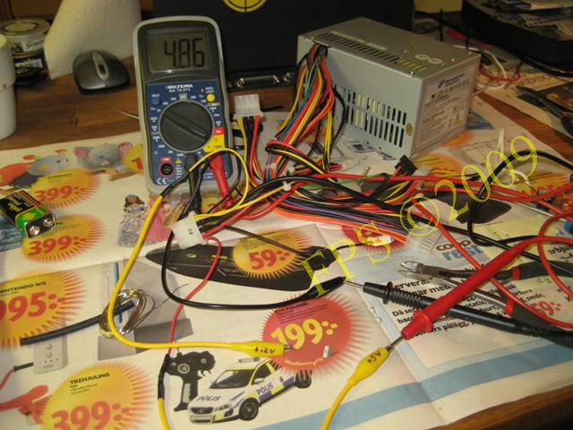
Here is crocodile clips attached on the cables for the floppy drive connector +5 VCD output.
Here is crocodile clips attached on the cables for the floppy drive connector +12 VCD output.
Note: Common is ground (GND - black cable) for both +5 VCD, +12 VCD, -12 VCD.
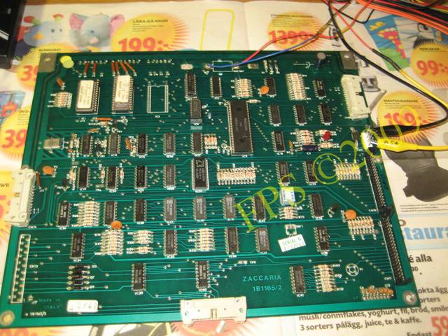
Here is the CPU board connected with +5 VCD from the transformer. Contact CN9 pin #4 +5 VCD and pin #2 ground.
 |
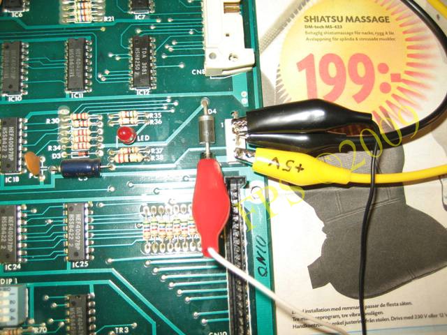 |
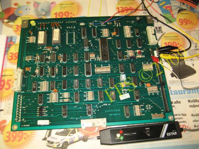
Here is a logic probe connected to the board to check the test points contained on the board. The logic probe need +5 VCD to work and should be connected to the circuit which is going to be tested. Attach the logic probes red lead to +5 VCD and the black lead to ground, in this case is red lead attached to the underside of diode D4 and black lead to ground CN9 pin #2.
When I supply the CPU board with voltage, I get it to start up and the red LED is constantly lit as it should do, verified with the logic probe I first read a LOW signal (0 VCD) and then HIGH signal (+5 VCD). When I attach a logic probe to the test points on the CPU board I read correct logic signal as below table,
| Test point | Signal | Purpose | Measured value |
| TP1 | High | CPU Pin 1- Sense | High |
| TP2 | Pulsing | CPU Pin 38 - Clock | Pulsing |
| TP3 | Pulsing | Interrupt Generator | Pulsing |
| TP4 | Low | CPU Pin 16 - Reset | Low |
| TP5 | High/Pulsing | CPU Pin 17 - Intreq | High/Pulsing |
| TP6 | Pulsing | Out Counter | Pulsing |
| TP7 | Low | Out Counter | Low |
| TP8 | Low | Voltage Good | Low |
| TP9 | Low/Pulsing | Clock Oscillator Good | Low7Pulsing |
The above results indicate that there should not be any problem with my CPU board, in addition I measure on CN9 pin #3 +4.07 VCD and this should indicate that there is nothing wrong with the power failure circuit on the CPU board.
NEXT STEP
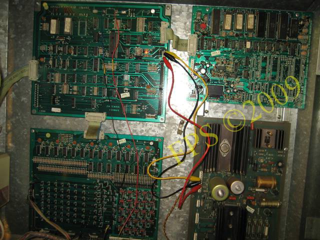
I use crocodile clip test leads to connect power board with the CPU board, connectors CN5 and CN9, leaving the white wire, which is for the power failure, unconnected between the boards, what we see is that the CPU board boots up and the red LED lights constant. This should indicate that I have problems with the tolerances of the various voltages in the power board, I suspect either the voltage 156.6 VCD to displays or even a defect in IC1 LM339 on the power board which controls the voltage monitoring circuit.
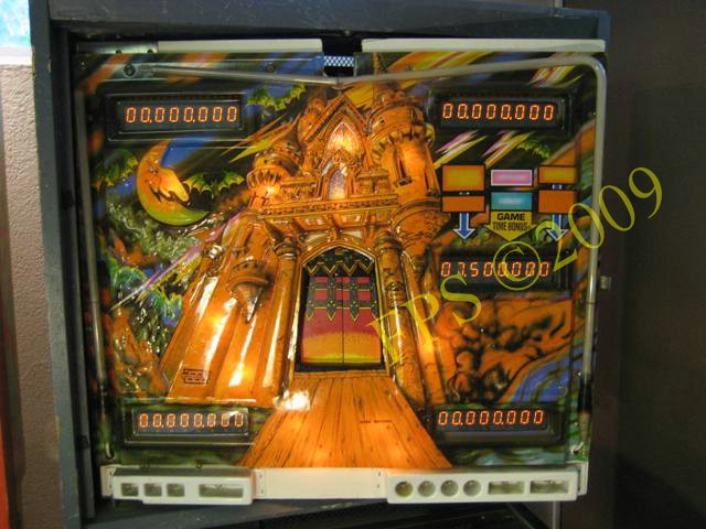
Now when the CPU board is up and running correct the displays is lit for the first time.
IT IS ALIVE AND SHOWS WHAT IT IS ABOUT - A HAPPY FEELING!
 |
 |
To get past the white wire (power failure) between CN9 pin #3 and CN5 pin #6 I connect the female connector (CN5) on top of my test cables as shown in the pictures above. Then I can also connect power to the driver board and the sound board. By doing this I avoid the CPU board to fail, not starting up as before, due to the power failure circuit. Now I can test the pinball's built-in test functions for the solenoids, lamps and sound. All sounds and voices from the sound board works and all the functions operated by solenoids such as slingshots, bumpers, drop targets, kick out hole, react flipper also works. The only thing that does not work in test is the lamps in the inserts, the logical lamps on the playfield. Although I manage once to get all the playfield lamps to flash in attract mode. I can start a game by pressing the service button in the cabinet and play on the machine. I do not know why but this can be a in-built function to test play the machine to see if there is any problems or just some wires wrongly connected which aloud me to start the machine. It turns out that the left flipper folds when hitting the ball.
Meanwhile this is a wonderful moment when I realize that this will probably not be an impossible project.
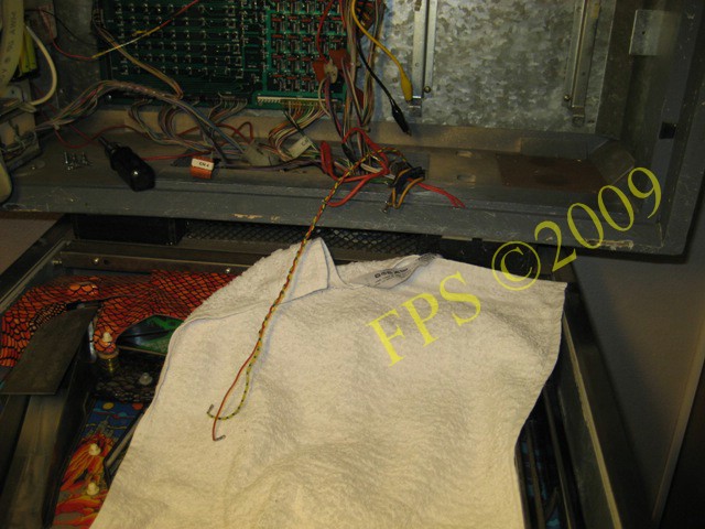
This suggests that the problems are related to the power board, which persists two options either to troubleshoot the power board, or try to find a working power board. Unfortunately I find it difficult to take out my board since CN1 is destroyed and all wires from the transformer are soldered directly on the backside of the power board.
POWER BOARD REPAIR
 |
 |
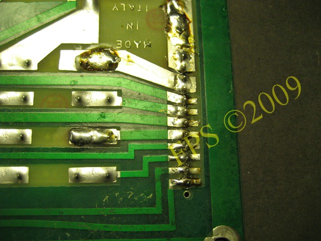
The wires from the transformer was soldered directly to the back of the board and it was a real mess. All wires was soldered away from the board to make way for a new Molex connector.
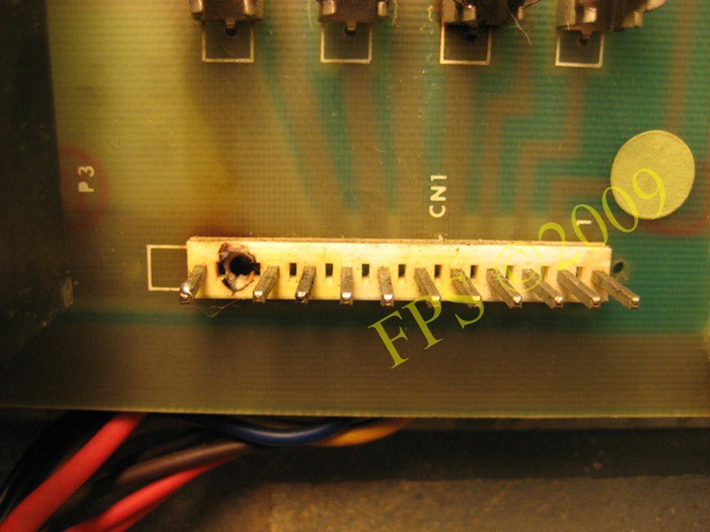
In the picture above we see the destroyed connector CN1, which is replaced by an 9-pin Molex connector with lock, (9-Pin Male Header .156 with Friction Lock).
In addition, there were two cables that went to a device at the coin door, (red wire 12 V, yellow/blue wire Ground), this is 12 V supply to a board with 3 blue cubes.
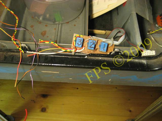
In the picture we see the device, I do not know what that is but perhaps some kind of counter?
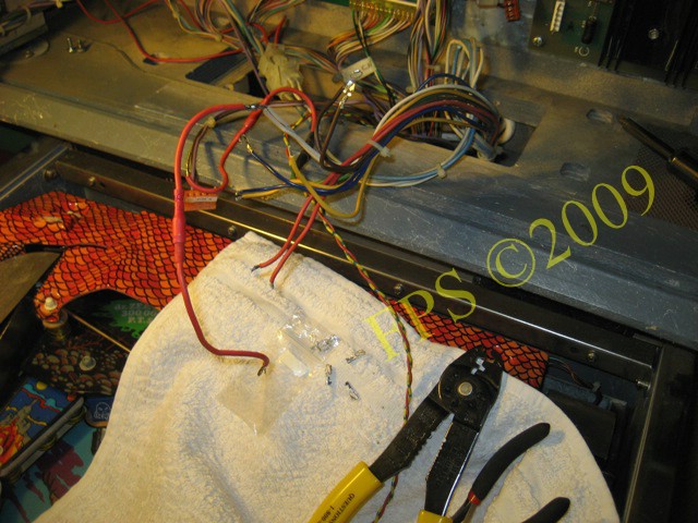
On each wire is terminals crimped on with a special crimp tool, terminals are then inserted into a female Molex connector housing, used terminals is Crimp Contact 0.156 in. Trifurcon 18-20 AWG Molex.
 |
 |
To remove the CN1 I cut it in pieces with a carpenter knife and heats the tin on the backside of the board.
Here I put the board on the edge between two shoe-boxes to facilitate the work to solder the new Molex connector.
 |
 |
Here we see the solder pads on the back of the board and the new Molex connector installed.
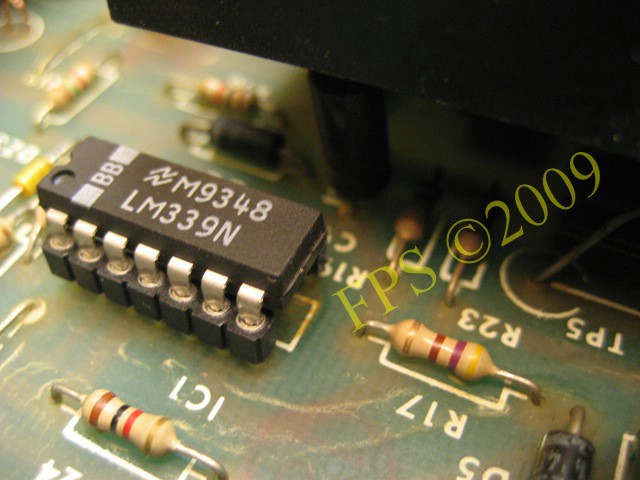
IC1 LM339 - PART OF THE MONITOR CURCUIT
Zaccarias generation 2 boards has a built in power failure circuit to secure that correct voltage is supplied to the CPU board before the CPU boot up. Point "B" and "C" in the circuit diagram are those that are monitored and this is done through IC1 LM339, although the transistor TR4-6 and the capacitor C9 is part of this circuit.
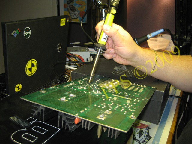
To be on the safe side that I solve the problem with the CPU board not booting up I change all the components since they all are inexpensive. In the photo above, I use an electric desolder tool with iron to solder away IC1 LM339.
 |
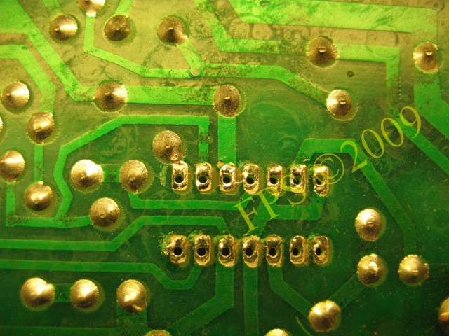 |
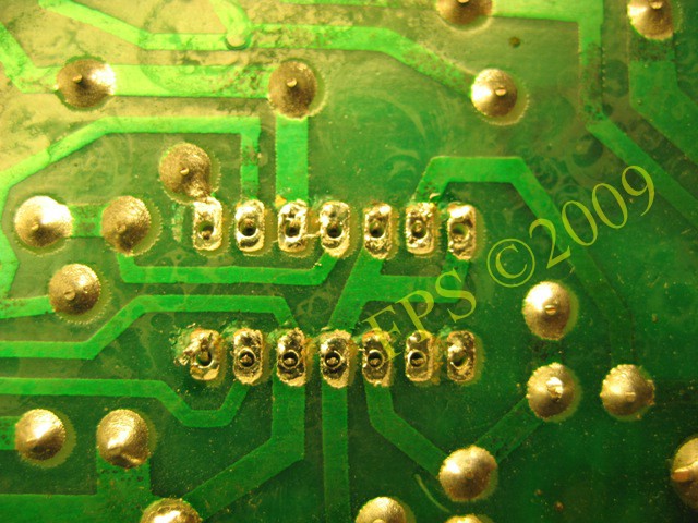
It is really effective and we can see how clean it is in the holes after the tin has been drawn up. IC chip fall out of the holes by itself without having to first cut off its legs and then coddle with a solder wick or a plain tin sucker.
I'm using a single-sided IC socket (IC Socket Strip 20 pin - Single in Line) that can be cut to the right number of legs for IC1 which facilitates the installation of the new IC chip or if it needs to be replaced in the future.
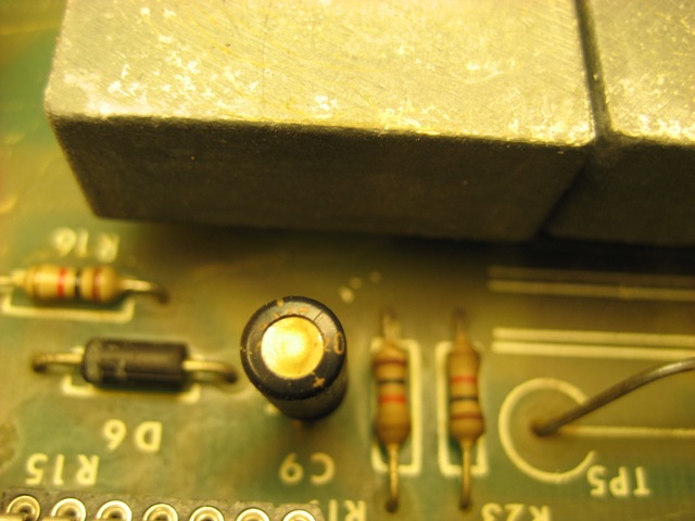
Capacitor C9 (1µF), I replace the old one which may have been dried and no longer work properly. If dried, this can cause ripple and the power monitoring circuit can then fail and the CPU will not boot.
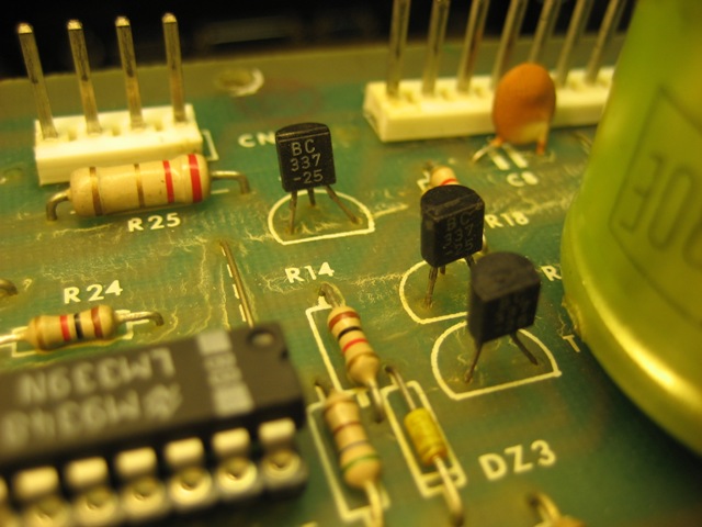
Here we see the three transistors TR4 (BC337), TR5 (BC337), TR6 (BC323) where the first is at the bottom of the picture. I replace all transistors with new ones so I am 100% sure that they work.
FINAL THOUGHTS - WRONG TRANSISTOR MIGHT BE THE CAUSE
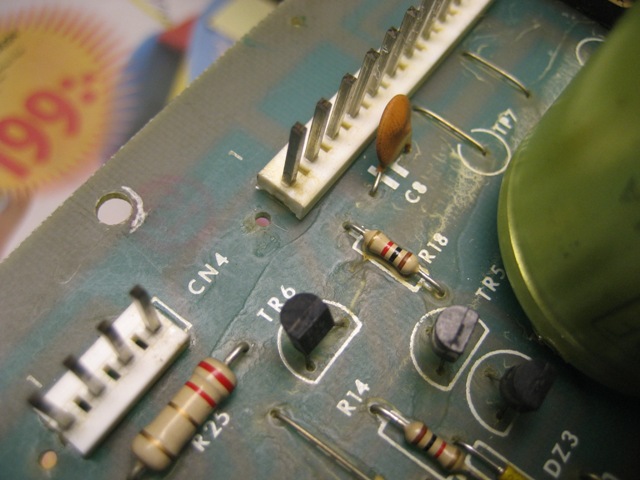
When I would replace TR6 (B323) I discovered that there was a BC337 transistor installed, and this may well be a major cause of why the CPU has not booted up. Since BC337 is rated for approximately 1A and BC323 is rated for approximately 5A we sufficiently understand why BC337 not have survived for very long time, which probably has resulted in failure in the power monitoring circuit which not allowed the CPU to boot up.
 |
 |
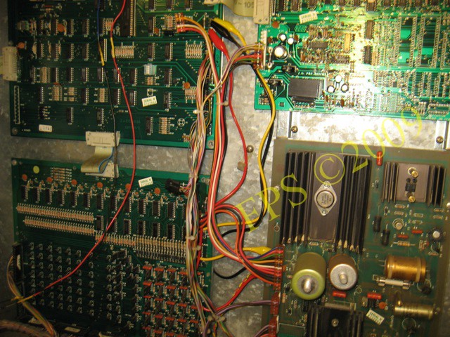
After all components has been changed on the power board and the power is switched on to the machine I again measure all test points (VCD) on the power board to verify that I have the correct values. Then I connect the other boards to the power board, be sure to have the main power off when dealing with the connectors. Then I again switch on the machine with all boards connected and the result is that the CPU boot and the machine is working. The red led on the CPU board shall lit and the red led on the sound board situated to the right of the CPU board shall not lit as in the right picture.
Now I have to figure out how credits can be added to the machine since it is not starting by pressing the start button in front off the cabinet. But it can be played by pressing the service button inside the cabinet, but only for a while until it resets.
THE STORY CONTINUOUS HERE
Reference: D. Gersic
Pleasure and Pinball
© FPS. All right reserved. |
Page Last updated:
2009-12-16 |