- Home Old school pinball <1985
- Grand Prix (EM) 1976
- Firepower (SS) 1980
- Space Mission (EM)1976
- Genie (SS) 1979
- Magic Castle (SS) 1984
- Black Knight (SS) 1980 New school pinball >1985
- High Speed (Sys11) 1986
- Earthshaker (Sys11) 1989
- CFTBL (WPC) 1992 Arcade Project
- JK-Cabinet with MAME Contents Space Mission
- Playfield Cleaning - Part 1
- Playfield Cleaning - Part 2
- Cabinet Refurbishing
- Backbox Refurbishing
- Refurbishing Diary
- Finsihed project
- Document - Flyer
|
Language |
|
|
WMS Space Mission (EM) 1976 Refurbishing project - Part IV!
WILLIAMS SPACE MISSION (EM) 1976 - BACKBOX REFURBISHING - SCORE WHEELS
 |
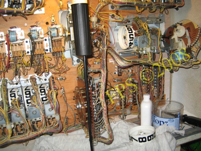 |
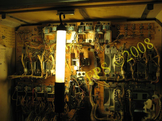
The pictures show the work with score wheels. Williams Space Mission use 16 units which need to be cleaned.

As usually there is a lot of dirt and unnecessary grease from lubrication, to be find on the unit. The three switches in the lower part of the picture is zero and nine position switches and the switch to the left is the (EOS) end of stroke switch.
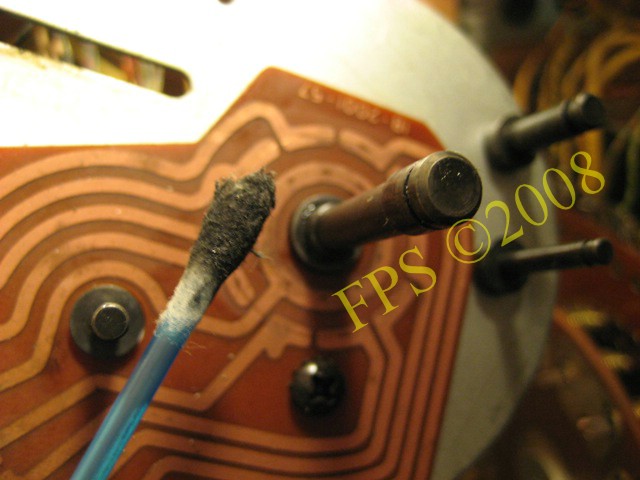
The q-tip has lot of dirt after cleaning.

On the rag soaked with Acetone used when cleaning the score wheel indicate how much dirt there was. Mention is that several rags was used per each Score wheel.
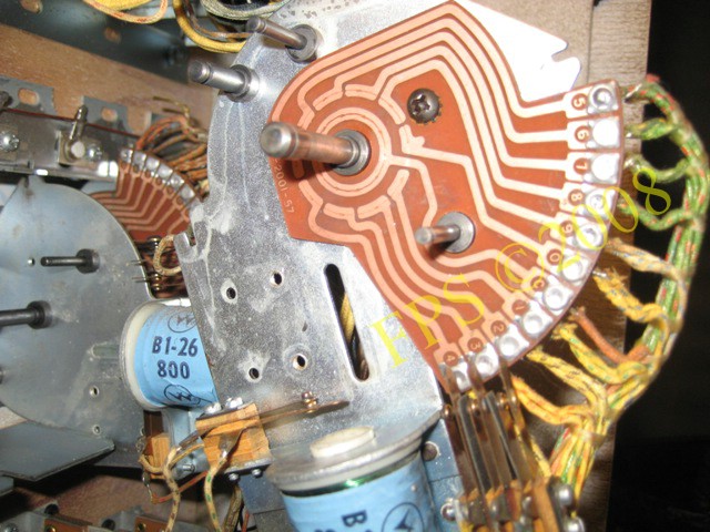
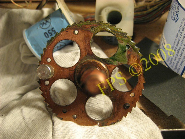
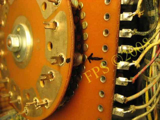
PCB Printed Circuit Board, the disc with different paths for the current to travel, is now cleaned from all dirt and grease from lubrication collected during all years of use.

Player 3 score reels disassembled.
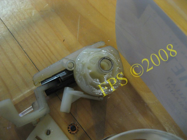
Urk, see how much grease there was on the ratchet do you remember the plastic/plastic rule there is no need of grease since there is a sort of dry lubrication between the nylon parts. The drive pawl is positioned against the ratchet cogs and move the score reel.
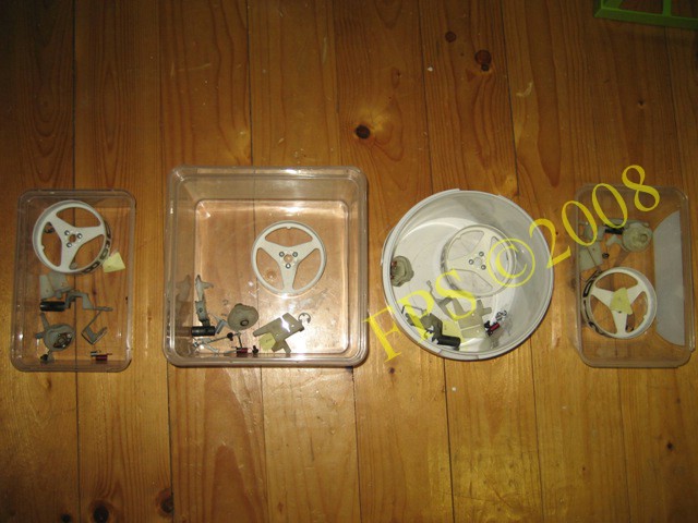
All parts from each score wheel is stored in a box with a label with number 1-4 to get the same parts on right score wheel after cleaning.
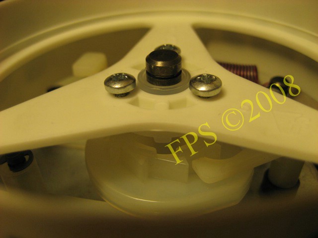
When drum reel shall be fitted to the ratchet (with switch blade if PCB is present) the tap on the drum reel shall be fitted to the step on the ratchet. Then the drum reel will be correct positioned and show number 0 in the window in the backglass when all three zero position switches is in open state.
Player 1 score reels cleaned, we can see number 5 pointing towards the coil which means that the number 0 is visible in the windows on the backglass. All three switches is now open, check that the distance is around 1 mm between the switch blades in open state. By manually moving the unit by pressing in the score reel coil plunger by hand the switches can be checked to open and close according to,

A cable came loose when I gently pull it. It is not unusual that cables is on the way to come loose form the soldering point due to all vibrations and stress that occur in the machine during play. I will mention that one cable on the right bonus unit come loose on mine Grand Prix some months after refurbishing causing the ball to stay in the right kick out hole during play.
Player 1 & 3 score wheel after cleaning.
Player 4 score wheel after cleaning
BACKBOX REFURBISHING - CREDIT UNIT
The credit unit was gummed up when I manually stepped up the unit. It almost not moved when stepping down the unit without my help which indicated that it needed to be disassembled and cleaned.
We can see the other side of the credit unit with the wheel which shows the number of available credits through the window in the backglass. As well as on mine Grand Prix is the wheel cut to limit the amount of credits. It is unusually to find a wheel with higher number then 8-10 on a electro mechanical pinball in Sweden. The wheel was probably cut to limit the amount of played credits, either by the operators or due to any law requirements.
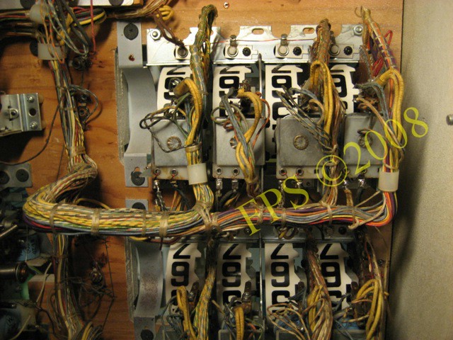
BACKBOX REFURBISHING - RELAYS AND JACKS
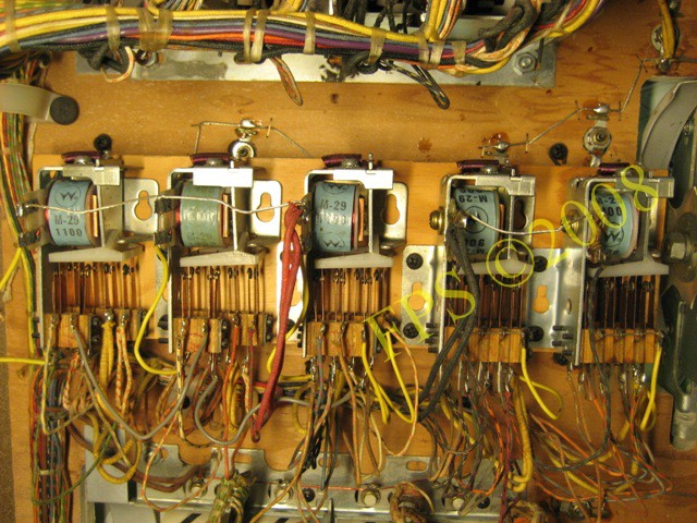
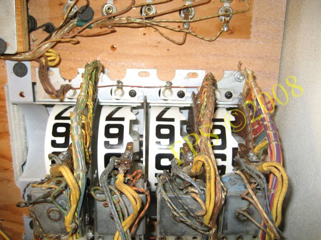
The first three relays form the left is in order 1000 point, 100 point and 10 point. These relays is energized by impulse from different switches on the playfield as swinging target, spinner, rollover switches, bonus relay, bumper switches. The two relays to the right is in order 3&4 reset and 1&2 reset, which pulse the drum unit thru zero switch on each unit. The reset relays is energized by impulse cam switch A on the score motor thru switch on the reset relay on the mechanism panel.
 |
 |
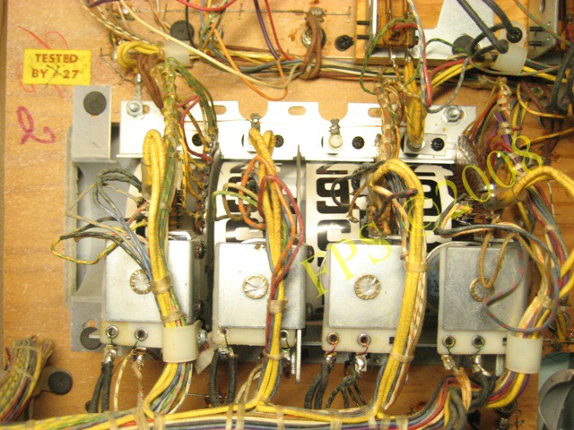
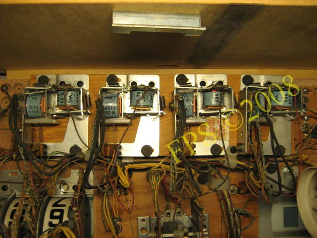
On the picture are the relays to indicate 100.000 points for player 1-4 when the score wheels has reached 99.990 points. This is a hold relays and after beeing activated they stays energized until the end of a game.

Jacks between backbox, playfield and the mechanism panel in the cabinet. These shall be cleaned to secure a good function in the machine, see further my Grand Prix Refurbishing Project.
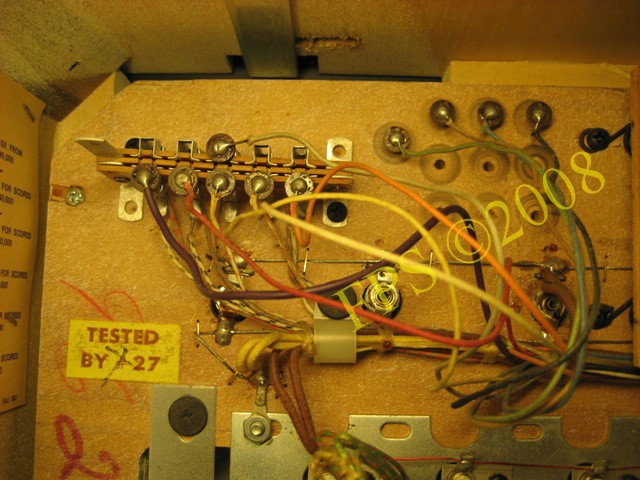
Jacks for adjusting x-tra ball or credit when a certain amount of points is achived.
BACKBOX REFURBISHING - MATCH UNIT

Match unit before cleaning.
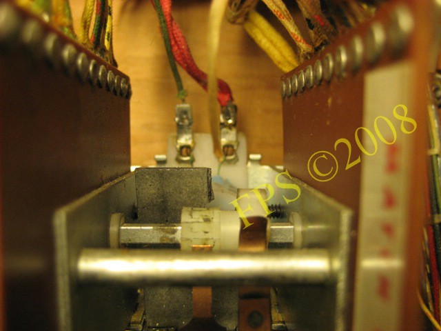
The metal activator plate was broken and needed to be replaced. Luckily I had a another match unit on my hand so I could use that metal activator plate as spare. A coil pull in the metal activator plate. On the metal activator plate a small nylon lever is attached which moves a small nylon gear on the rotating shaft to advance the match units contact wipers.
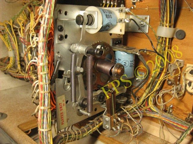
BACKBOX REFURBISHING - PLAYER UNIT
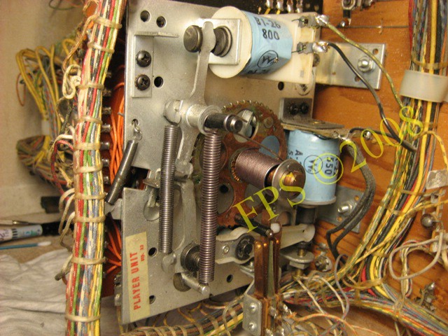
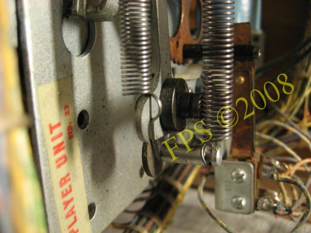
Player unit before cleaning.
Take a lot of pictures before removing parts from the unit to remember how it was situated before the cleaning. For example how the switch was positioned. There is also a possibility to look at similar units or relays to remember when reassemblies the parts.
 |
 |
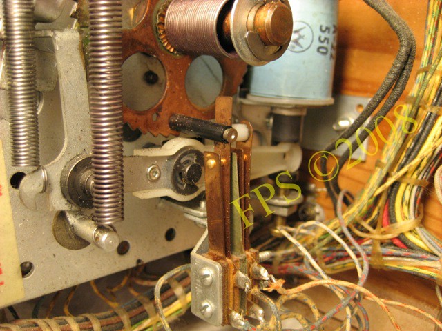
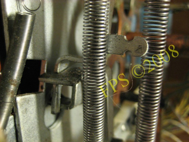
Before disassembly of the player unit make a mark with a marker pen where the spring was attached to the ratchet and shaft assembly. When loosen the spring it is important to count the springs pre-tension, count how many turns the spring is loaded with then you can apply the same amount of turns when reassembly the unit. Normally it is 3 turns sometimes 4 turns if the spring has started to be weak.
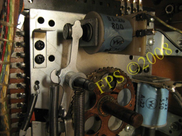
There was a lot of old grease on the ratchet and shaft assembly which has been hard as cement. When reassemblies put a small amount of Super lube on the edge of the cogs.
 |
 |
The spring who makes the plunger to move out from the solenoid was weak. I had to replace the spring 10A-228 with a spring that I had on hand. Mention is that these springs is hard to get so I used a similar spring, unfornately not original.
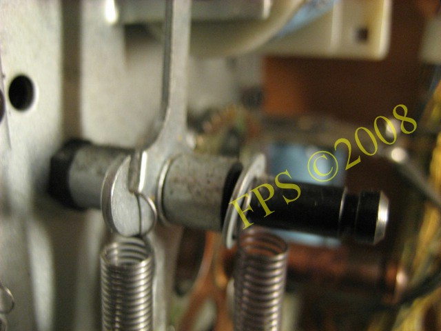
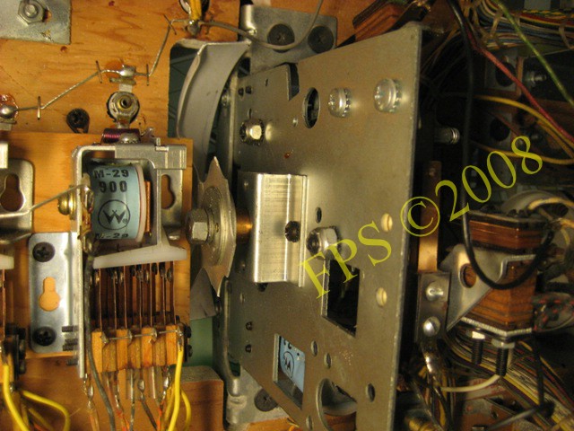
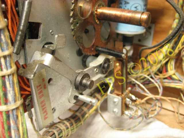
Picture to remember how it was before taking unit apart.
Before removing the disc is it marked with a pencil in the reset position. If the disc not can be moved to the reset position due to gummed up mark and put it in the same position as before when reassemblies. This is to avoid position the disc 180 degrees wrong.

Before attaching the disc apply a thin layer of grease preferable Super Lube to the backlit disc rivets. This film of Super lube will prevent the rivets from getting corrosive and they will get more conductive also the stepper unit will work more smooth. The Super lube also prevent the rotating fingers from wearing out the rivets.
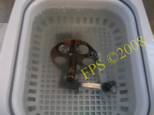
Here we can see how the dirt come off the parts in the Ultrasonic cleaner. It looks like a cloud in the water to use the Ultrasonic cleaner is a real treat.
BACKBOX REFURBISHING - LABELS
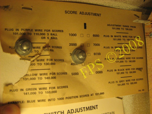
Table inside backbox for score adjustment can be adjusted for x-tra ball or credit same player shoots again.
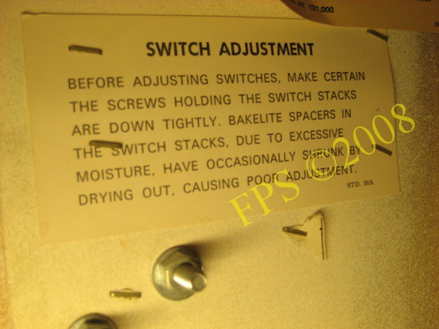
Label with information about switch adjustment inside the backbox. The rule is to be sure that the switch is in need of adjustment. If adjustment really is needed it can be judge by looking at similar relays or switches. If more then 10% of the total amount of switches in the machine has been adjusted there probably is more or even worse problems then before starting adjustment of switches.
SWITCHES
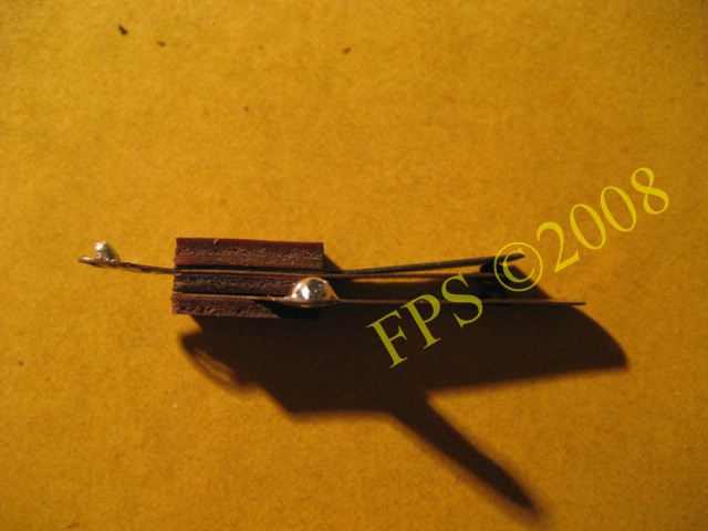
A pinball leaf switch consist of many parts which is build on two plastic tubings. Ingoing parts which can be combined in numerous variants is copper or tungsten switch blades, plastic/fibre spacers, insulator paper, solder lugs.
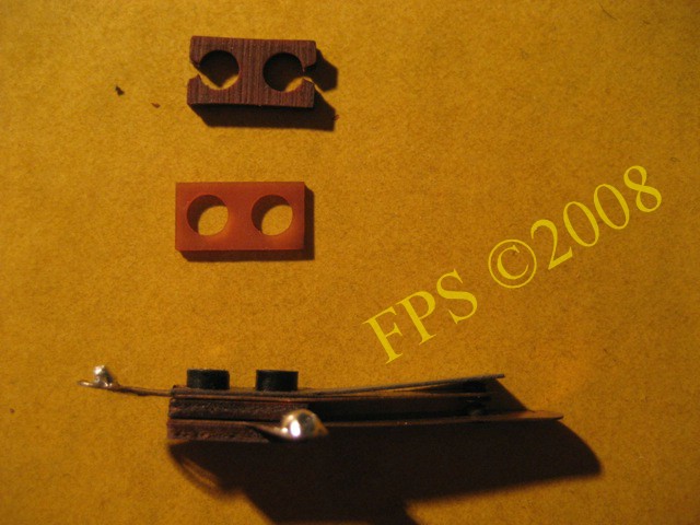
Here is two spacers removed from the switch.
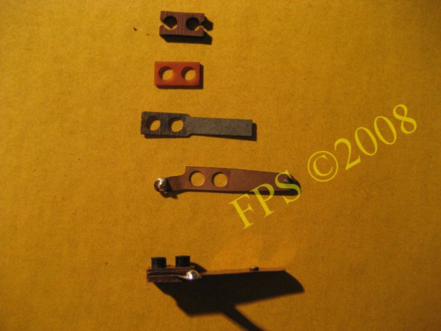
Here is one of the switch blade and insulator paper removed from the switch - the insulator paper is used to for example insulate the switch against a wire form on the playfield.
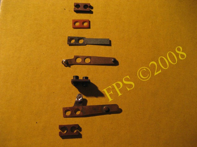
Now is the second switch blade removed and the complete switch is disassembled in several parts. As earlier mentioned a switch can be build up by combining various numbers of spacers to achieve different distance between the leaf switch blades. This can be useful when installing new switches for the flippers in the cabinet to achieve optimal closure of the leaf switch blade when the flipper button is pressed.
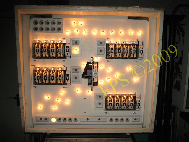
Backbox without backglass. Finally all lamps is replaced from #44 to #47 and score wheels is cleaned.
Pleasure and Pinball
© FPS. All right reserved. |
Page Last updated:
2009-03-18 |