- Home Old school pinball<1985
- Grand Prix (EM) 1976
- Firepower (SS) 1980
- Space Mission (EM)1976
- Genie (SS) 1979
- Magic Castle (SS) 1984
- Black Knight (SS) 1980 New school pinball >1985
- High Speed (Sys11) 1986
- Earthshaker (Sys11) 1989
- CFTBL (WPC) 1992 Arcade Project
- JK-Cabinet with MAME Contents Genie
- Playfield Refurbishing
- Playfield Painting
- Cabinet Refurbishing
- Electronics
- Before-After Pictures
- Refurbishing Diary
- Finished project
- Dokument - Flyer
|
Language |
|
|
Gottlieb Genie SS Refurbishing project - Part IV!
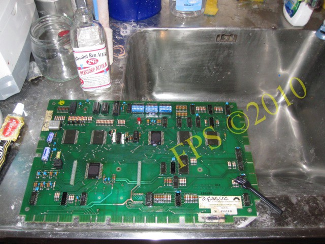
POWER BOARD - MANDATORY FIX
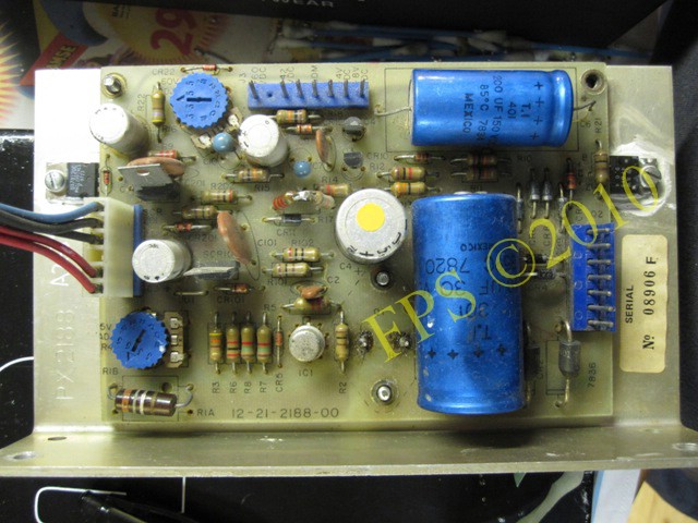
The power board is mounted on a metal L-frame and make repair a little bit tricky.
 |
 |
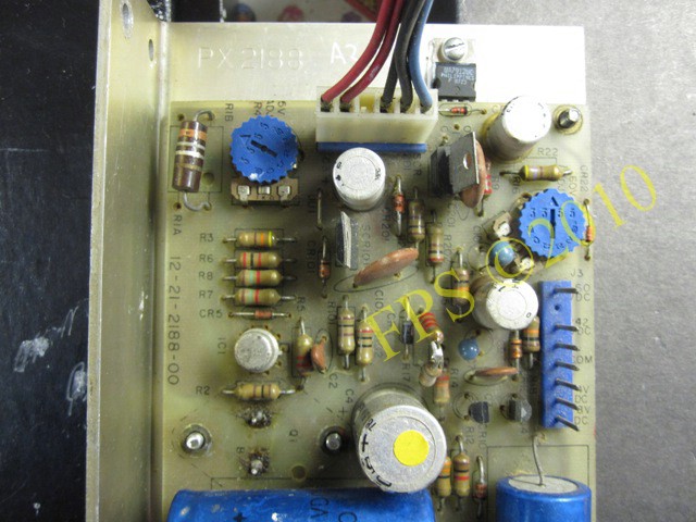
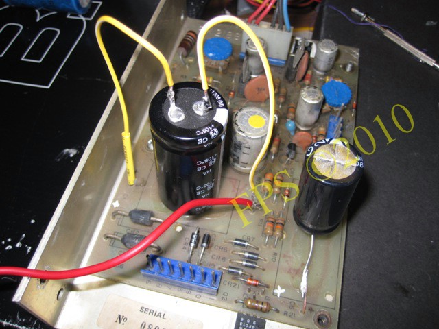
In the picture to the left we see the two trim potentiometers R4 (adjust to +5 volt) and R16 (adjust to +60 volts). The connector at top of the board is for +5 (red wire) and -12 (blue wire) volt power supply for the CPU board and the connector on the right side is for power supply to score displays, +60 and +42 volts.
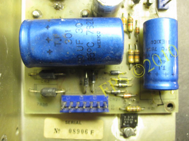
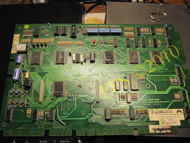
The large electrolytic filter caps on the power board is +30 years old and has probably dry out which can result in strange behaviours for the power supply of the CPU and driver board, caps is situated on the bottom part of the board seen in right picture.
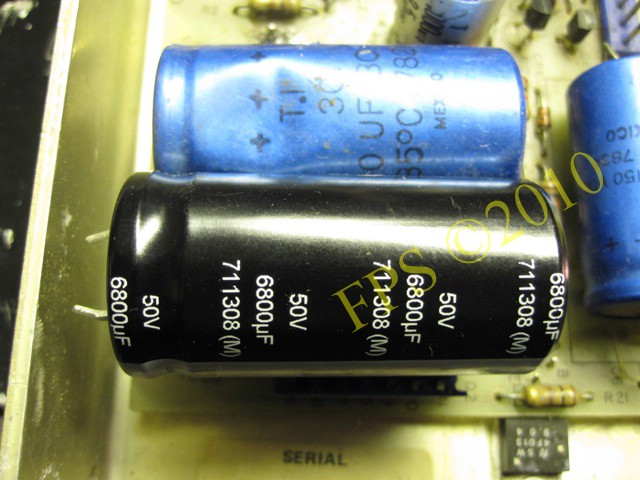
I replace the large +5/12 volt filter capacitor C1 2900 mfd with a 6800 mfd 50V capacitor.
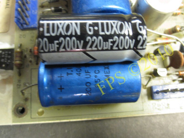
Also capacitor C6 200 mfd 150 volts is replaced with a new 220 mfd 200 volts, if this cap dries out it causes the score displays to go dim or flicker.
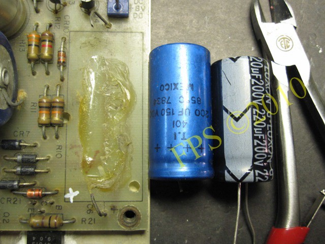
The capacitors is glued on to the board so they need to be cut away with a razor blade.
Working with the power board.
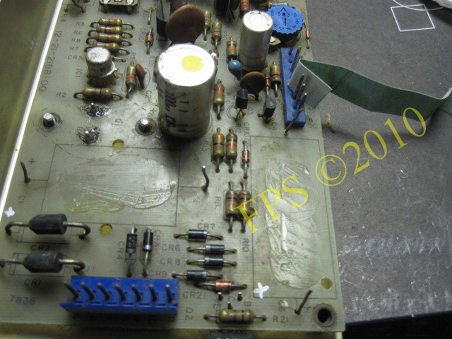
Before installing the new capacitors the board is cleaned and the connector pins is sanded with #240 grit sandpaper. The trim potentiometers are cleaned with contact cleaner and then blow with compressed air.
The result after working with the power board. New capacitor C6 220 mfd is soldered on the old legs of capacitor and the large C1 6800 mfd is glued on the board with melt glue in a standing position. Also the red ground modification wire is attached to the minus side of the large capacitor.
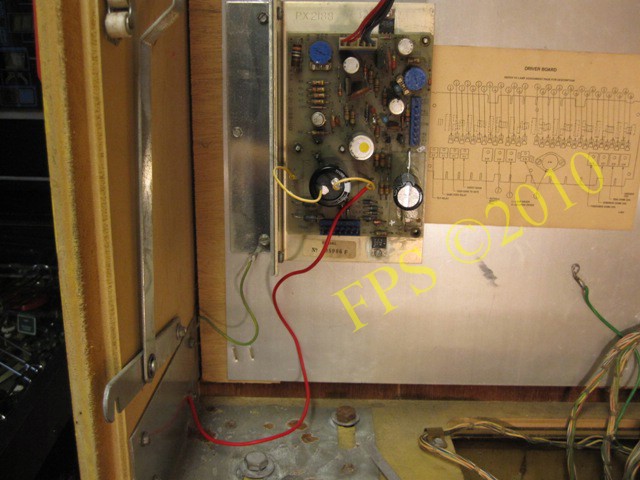
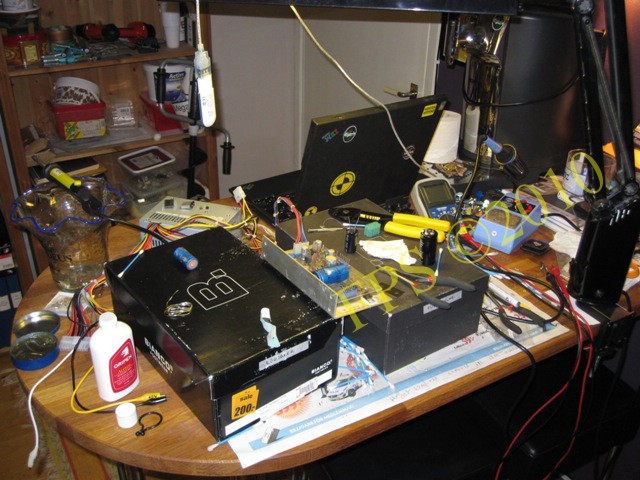
Then the board is installed in the pinball and the output voltages is verified with a multimeter. Also notice the red wire which is an extra ground modification. Also the CPU board (wire attached at minus side of capacitor C16) and driver board (wire attached at minus side of capacitor C1) need this extra ground wires to eliminate ground problems which can cause strange behaviours of coils.
BRIDGE RECTIFIER
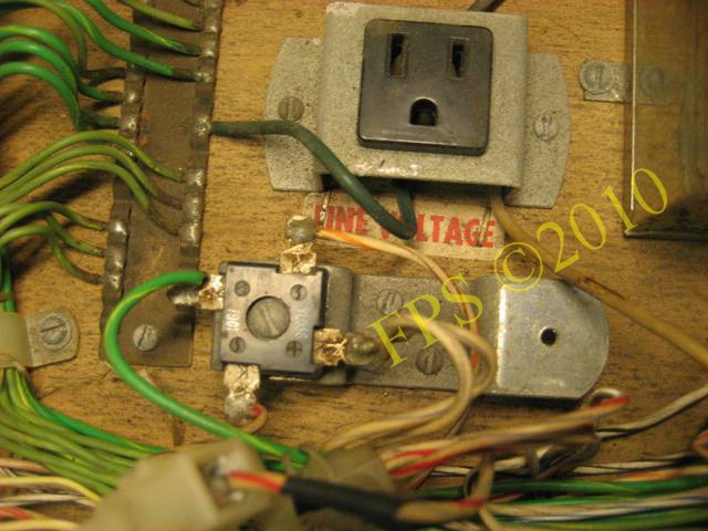
One of the two bridge rectifier (35 amp 400 volt) on the bottom panel was missing. Left bridge is for CPU controlled lights 6 volts and right bridge is for playfield coils 24 volts.
Argh - McGywer has again made an quick n dirty fix on this pinball machine.

New bridges installed and the power line is secured. All fuses is replaced with new one and are situated below the bridges, two fuses to be found on the underside of the playfield.
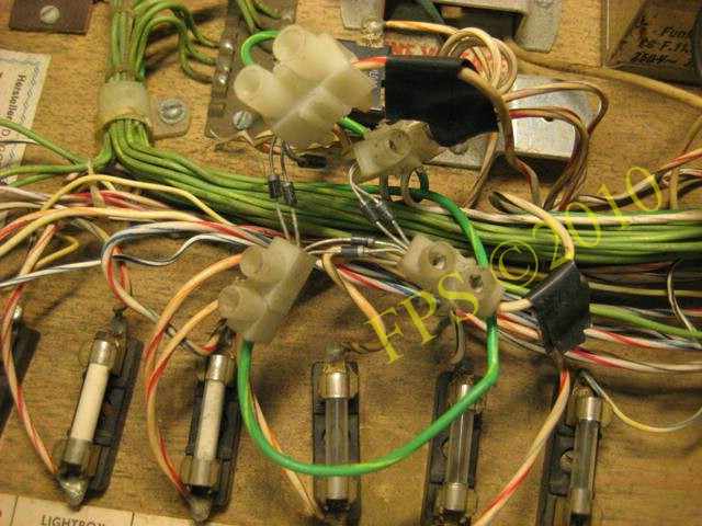
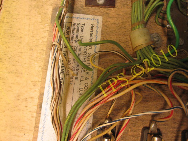
CHECK FOR BROKEN WIRES
 |
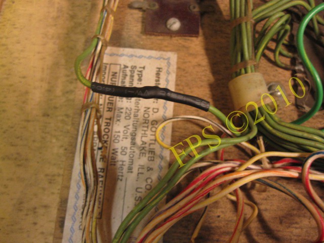 |
Check for broken wires.
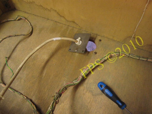
POWER COORD LINE
 |
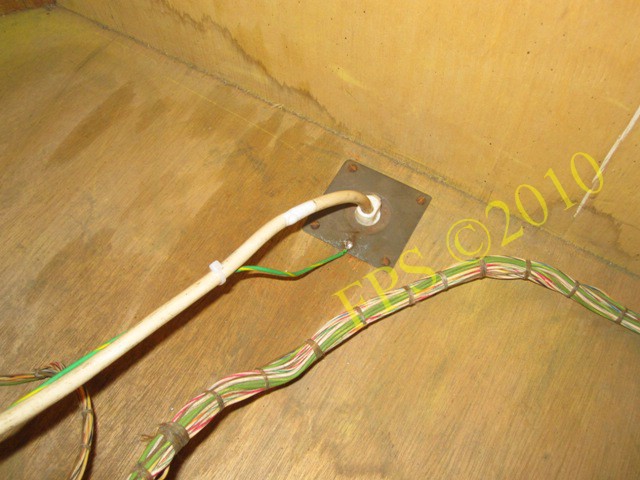 |
The 220 volts wire was loose and the ground wire was to short.
CPU BOARD ROCKWELL - SPIDER CHIPS FROM HELL
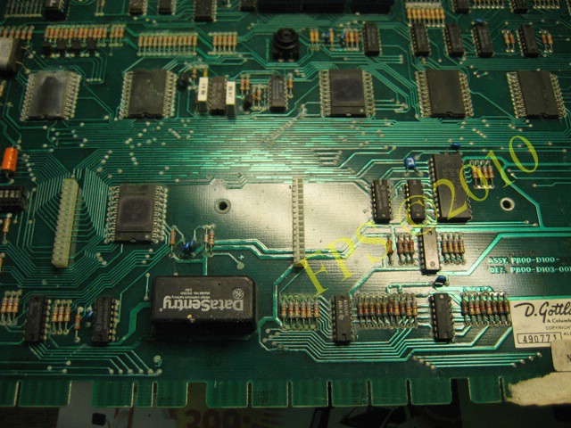
The CPU board was in bad shape in the area around the battery. Gottlieb used a recharable DataSentry 3.6 Volt battery and after +30 year the battery start to leak battery acid. The CPU boards components and connectors around the battery had corrosion from battery acid. This is a MANDATORY fix. Replace it with a remote battery pack. The remote battery pack can be mounted on the inside of the door in the backbox to guarantee that no battery acid will leak regardless if the batteries is new or old. It can occur that new batteries that is slightly used can havoc and leak battery acid.
 |
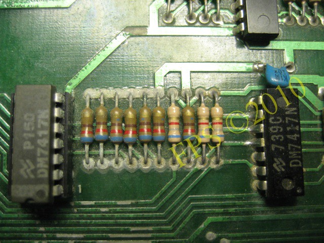 |
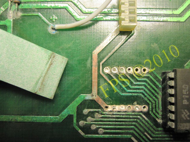
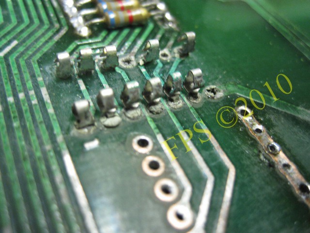
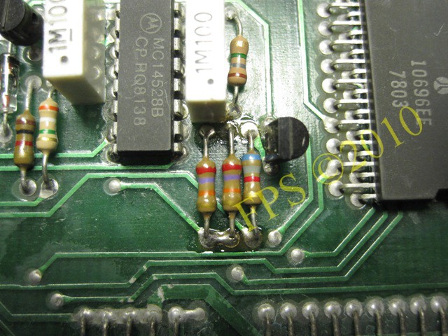
Here we see what these battery can cause, if any components lead is grey or green replace the part without any hesitation.
The resistors leads is cut to make the de-soldering easier. Then I use an electric de-solder tool with iron to remove the solder so I then can gently pull the cut off lead out of the board.
 |
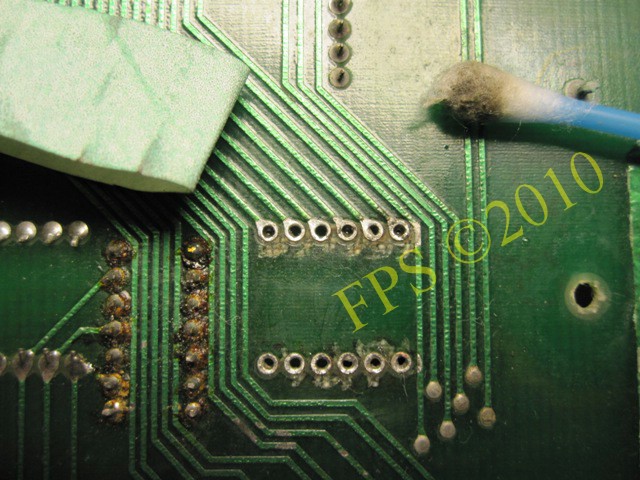 |
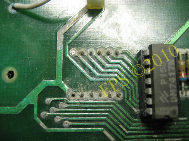
The traces is then sanded with #240 grit sandpaper on both side of the PCB.
Cleaning with Q-tip soaked in Acetone.
 |
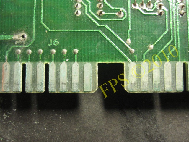 |
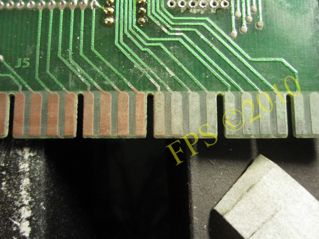
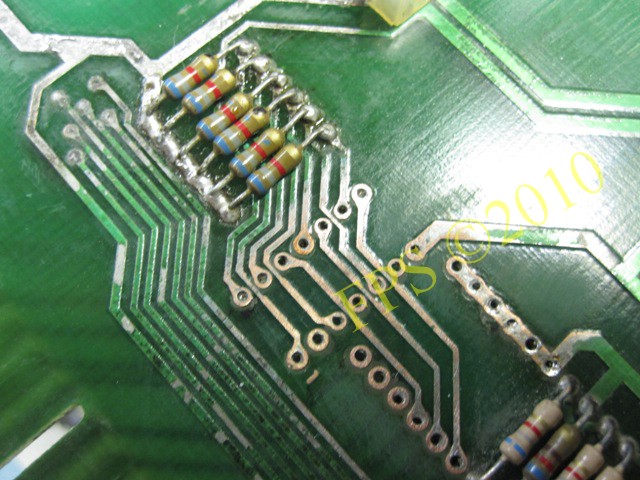
The edge connectors fingers on the CPU board had also corrosion and needed to be sanded to the copper was visible.
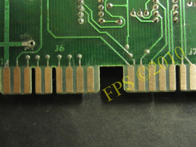
You need to sand a lot to get the edges back to copper.
 |
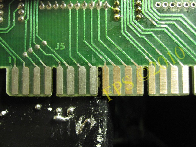 |
Above - New solder applied on the edge connectors.
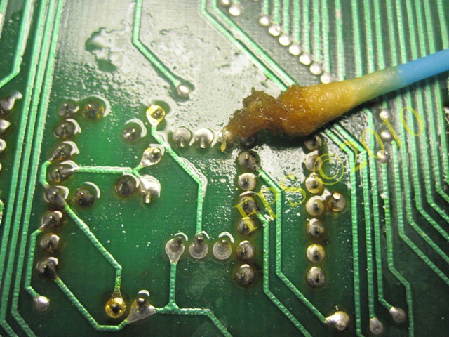
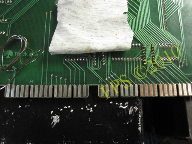
The PCB board is washed with a mixture of 24% vinegar and water 50/50 to neutralize and remove the corrosion. Pour mixture on the board and scrub with a brush and then rinse the board with water, I used battery water (demineralized and deionized). Last step rinse the board with alcohol to dissolve/evaporate the water.
I will try to get this CPU board to work but it will require a lot of hours of work and a large portion of patience. The biggest problem will be that I do not have any testing equipment that can identify problems on the board so more or less I have to troubleshoot the board by swapping components. Eventually it is possible to measure some components and see if they are defective. The goal is to boot the card on the workbench and then see how it works in the pinball machine.
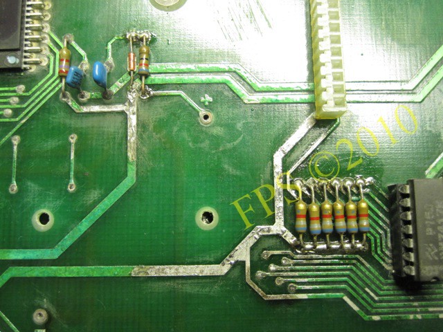
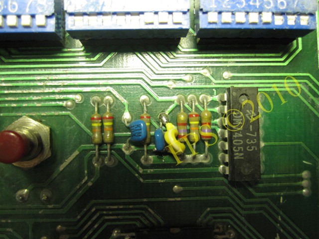
I replaced 6.8 Kohm resistors that seems to have problem due to battery corrosion.
 |
 |
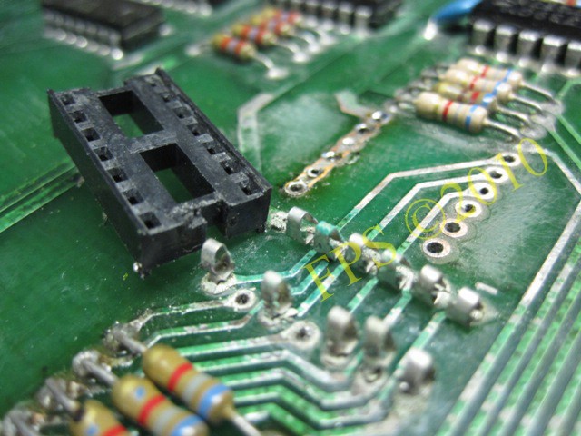
I changed the socket for IC Z5 which were badly corroded.
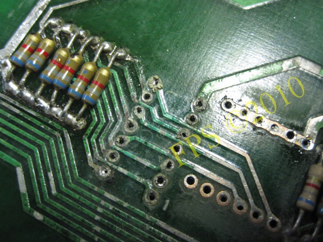
Here we see how green the solder pads on the CPU board was.
 |
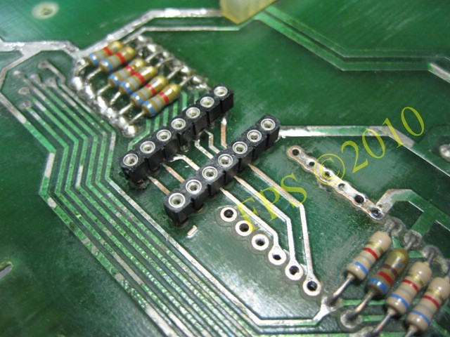 |
Sanding with #240 grit sandpaper and then a new socket installed - I use IC socket singel in line is used.
I changed the components involved in the reset signal at power on, transistors Q5 and Q6 (MPS-A70) and capacitors C31 and C32. Also IC Z2 4528 CMOS is part of the reset circuit but measured to be ok - +5 volt at pin 7 and 9 after one second of power on.
To defeat the slam switch permanently a jumper is soldered across the C2 cap. Gottlieb used two slam switches in system 1 pinball which must be closed to get the machine up and running. If any of the slam switches is open the CPU board will not boot.
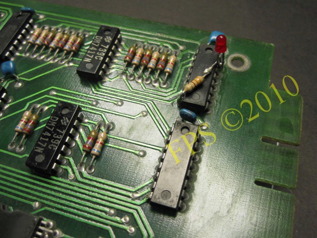
Here I have soldered a red led on IC Z16 pin 8 and 15 to simulate the pinball displays. On pin 8 (ground) a resistor is connected (330 ohm 1/4 W) which then is connected to the red led, second leg of the red led is connected to pin 15 of the Z16. When the CPU board is powered and after a 5 second delay the red led should light up.
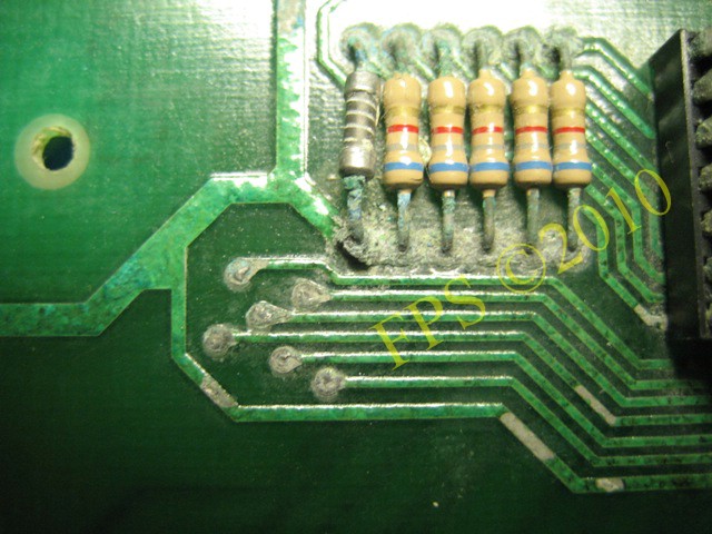
CONNECTORS - TERMINAL PINS
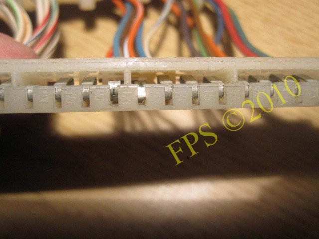
Some of the terminal pin in the edge connectors are broken and corroded and many are so compressed that they never would touch the CPU edge connector surface. See the example in the picture above, there is about 100-200 terminal pins to be replaced in these connectors.
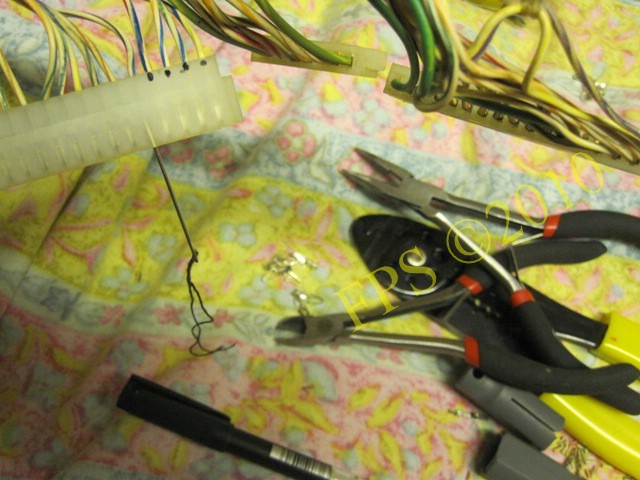
To remove the terminal pin I use a sewing needle which I push in between the terminal pin and the plastic connector housing. Pull the wire with the terminal pin gently and it will come out of the connector housing.
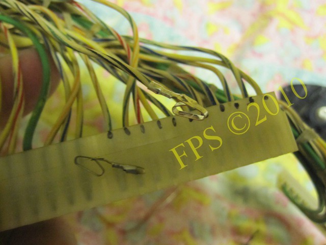
I replace each terminal pin one at a time to avoid mixing up the wires in the connector housing. Use pin, Molex 0.156" single side connector pins # 08-52-0072.
 |
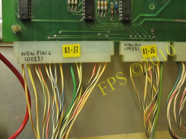 |
A1-J5, A1-J6 (slam switch signal), A1-J7.
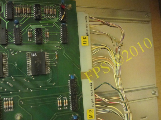
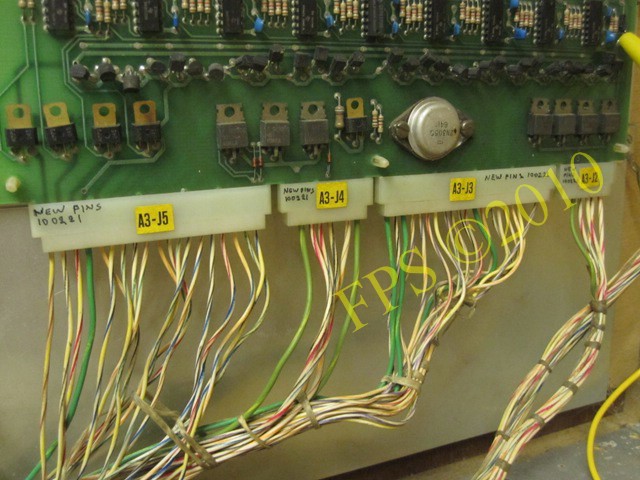
A1-J2 and A1-J3 for the score displays.
I AM NOT SURE WHAT IS GOING ON
 |
 |
After much work with the boards I start the pinball and get two displays to light but nothing else happens. General illumination in backbox and on the playfield lights without any problem. No fuse blows. So far everything is hunky and dory. I measure up correct values for voltages on the CPU board and voltage for score displays but there are still problems that make the CPU board not booting. I should consider whether it is worthwhile to spend more time and effort on trying to get life in CPU board.
Pleasure and Pinball
© FPS. All right reserved. |
Page Last updated:
2009-03-11 |