- Home Old school pinball
- Grand Prix (EM) 1976
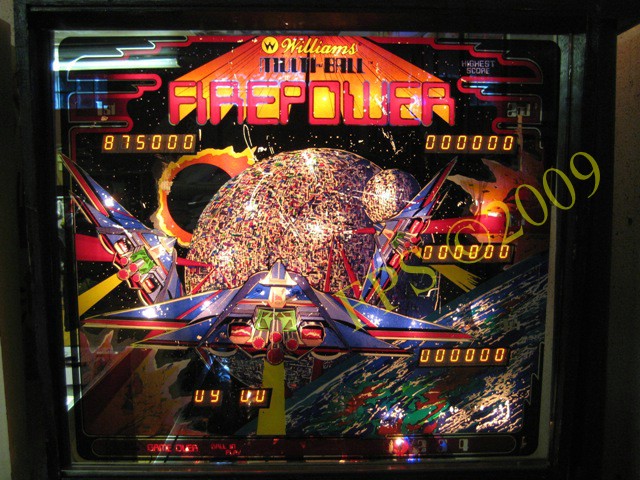
- Firepower (SS) 1980
- Space Mission (EM)1976
- Genie (SS) 1979
- Magic Castle (SS) 1984
- Black Knight (SS) 1980 New school pinball
- High Speed (Sys11) 1986
- Earthshaker (Sys11) 1989
- CFTBL (WPC) 1992 Arcade Project
- JK-Cabinet with MAME Contents Firepower
- Playfield Refurbishing
- Playfield Painting
- Cabinet Refurbishing
- Playfield Parts
- Electronics
- Refurbishing Diary
- Finsihed project
- Dokument - Flyer
|
Language |
|
|
WMS Firepower SS Refurbishing project - Part V!
FIREPOWER (SS) 1980 - ELECTRONICS
There where some electronic issues on mine Williams Firepwer 1980 and here I will try to describe the work.
Problems on this old machines can often be referred to the connectors. This old version of Molex connectors is situated on the PCB Boards. On the PCB boards the male connector is to be found and the female housing connector is connected to this male connector. All distribution between the boards and for example the playfield is going through this connectors.
There is a type of connector that consist of several Molex connectors in a row and this connector is called 40 pin Inter-board connector - this 40 pin Inter-board connector distribute the signals between the CPU board and the driver board. Williams worked out this solution to easier separate the boards for maintenance. Unfortunately this connectors will not be stable after many years of use and many problems can be related to this 40 pins story - mention that the signals for the data bus and the address bus runs through this 40 pin Inter-board Connector.
Something that annoying me was that the displays did not show all the digits. Display 1 and 3 showed only four of six digits and display 1 and 4 showed only three of six digits - the work to get all digits back on the displays appear to be a real challenge.
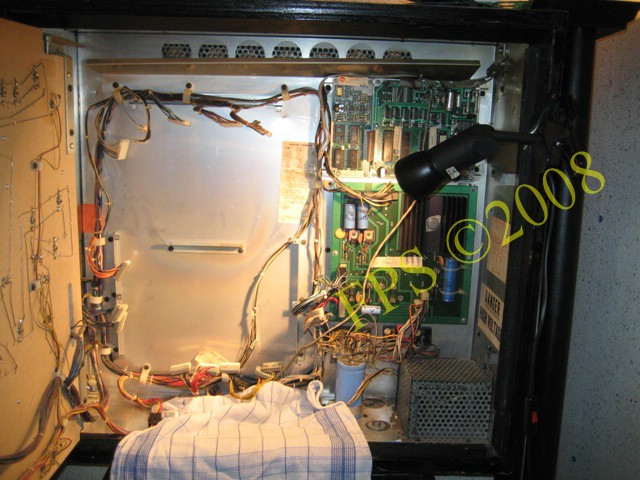
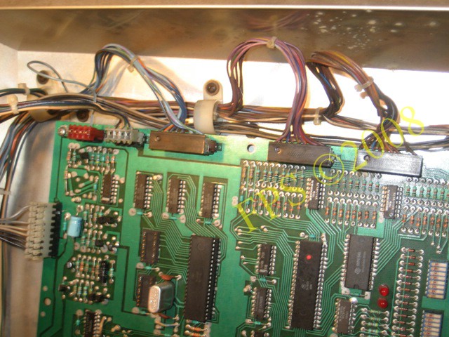
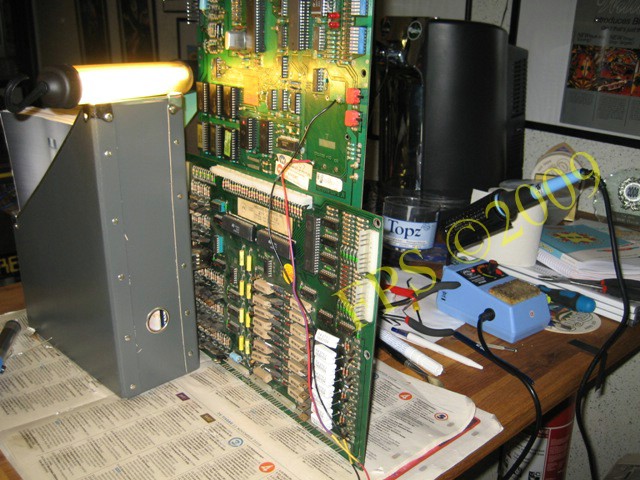
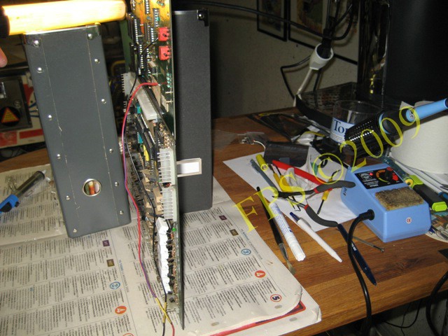
CPU AND DRIVER BOARD IN BACKBOX
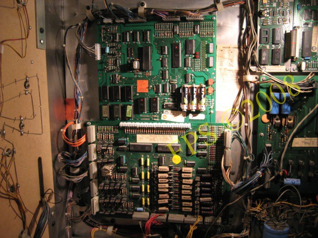
The driver board is connected to the CPU board through a 40 pins connector and is hanging on a metal bar in the backbox.
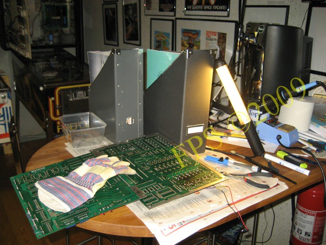
Boards removed from the backbox. We can see the metal bar which the boards is hanging on in the center and the vertical bars with screw holes for the boards.

Time to solder on the boards!
CPU BOARD CONNECTORS - Molex
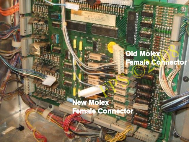
When I bought Williams Firepower 1980 it sometimes did not start in attract mode, during a game played it reset. I believe this strange behavior occurred due to play in the connectors on the CPU board. I had to open the backbox and bend or exercise the connectors to achieve power to the board and get the two red diodes to lit. Biggest problem was it with the 9 pins Molex connector - connector 1J2.
On the Williams System 6 CPU board, there is male connectors that has became bad during the years of use due to variation in temperature, dust and smoke and to the fact that they have been connected several times. The pins on the male connector has in many cases been resolder several times during the years. This create bad contact surface between the male and female connector. There is also a risk that the connectors soldering points has cracked which result in bad electrical conduction . When loosing a female connector from the CPU board the wire can come loose from the terminal or the wire has been bended.
Instead of doing a proper work to change the connectors the choice is to resolder the pins and the solder points on the PCB boards. This preventive measure is only a temporary fix and will not solve any issue in the long term.
The old type of Molex connectors has round pins with less contact surface. The Molex connectors of today has square pins which increase the contact surface.
It is recommended to at least change the male connectors on the boards from the round version of pins to the square version.
To remove the male connectors I cut them with a carpenter knife.
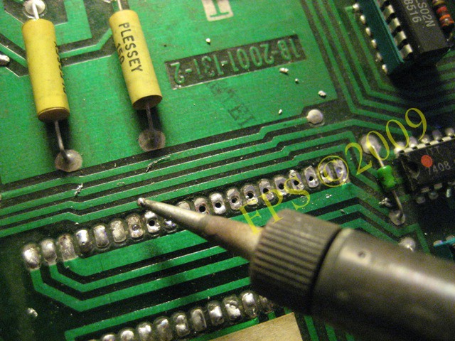
I added some new tin to the solder points to easier remove the old tin with a solder wicker or solder sucker.
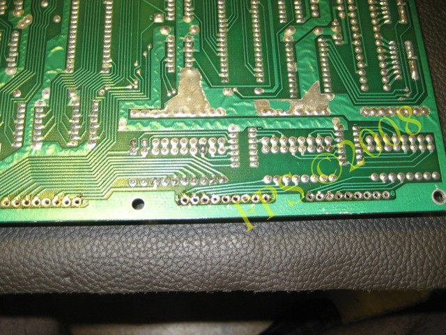
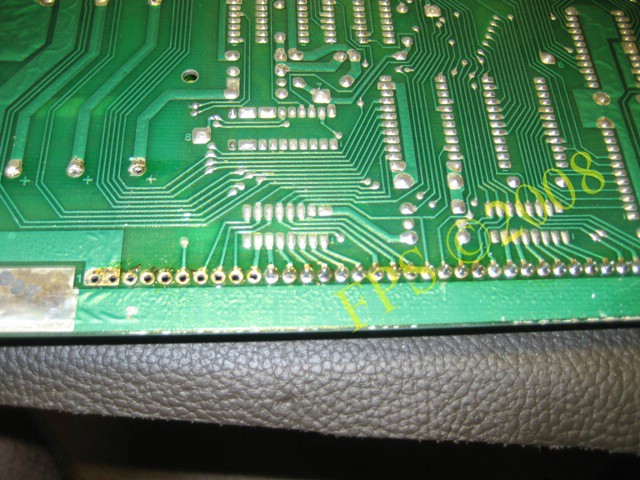
The picture shows the backside of the board where I remove the tin with the solder wicker. Apply adequate of heat until the solder wicker start to absorb the old tin. Be careful to not apply to much heat which can damage the boards printed etchings.
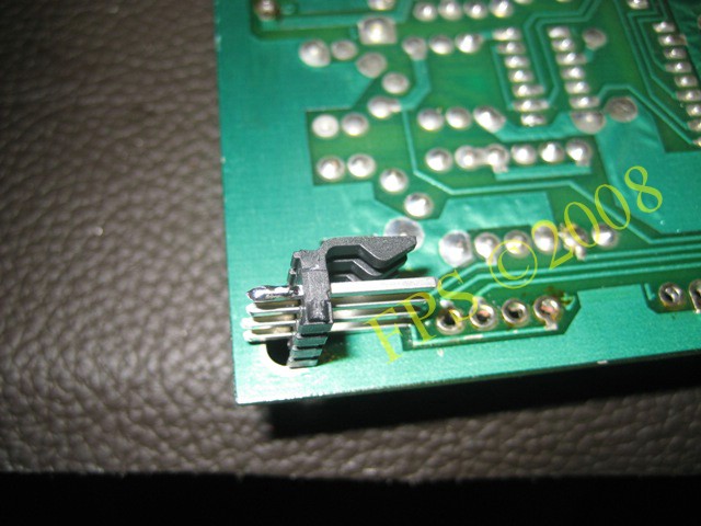
Then it is easy to remove a part of the connector without damage the board.
 |
 |
The complete connector removed without any damage to the solder points - printed etchings.
 |
 |
The new Molex connectors has squared pins instead of the old versions round pins which increase the contact surface.

I choose to replace all Molex connectors on the CPU board to maintained proper function. In particular the 9 pins power connector 1J2 was replaced.
Also the female housing of type Molex was replaced. The old version is known to be instable after many years of use - play in the terminals.
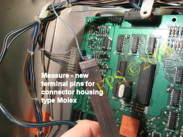
It is important to measure correct length for cutting of the plastic isolation to achieve proper crimping of the wire strands to the terminal.
The picture show two Molex connectors of today version.
In the upper right of the picture we can see some of the tools used when working with the boards - long pile cutter, different files.
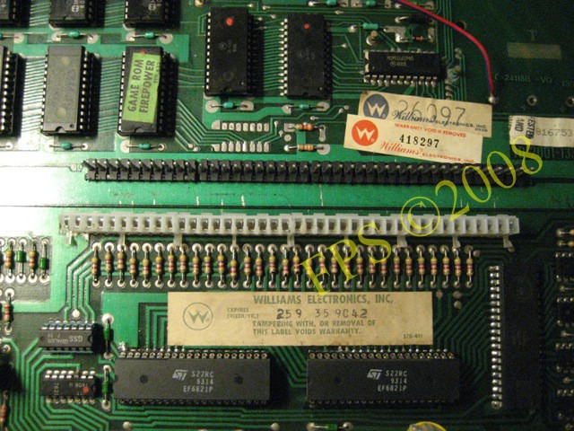
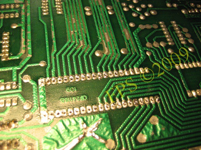
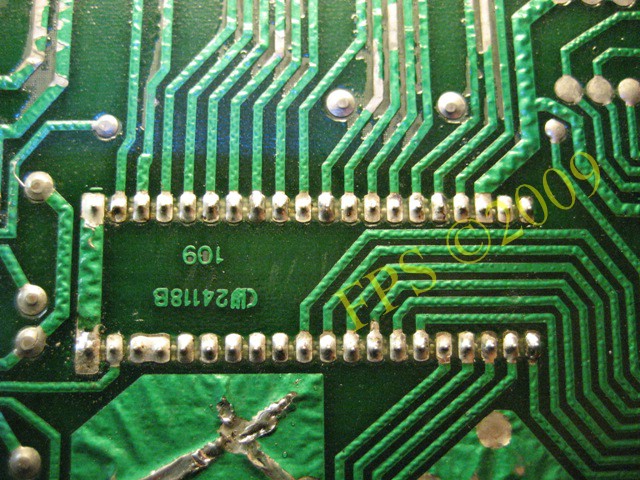
40 PIN INTER-BOARD CONNECTOR
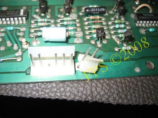
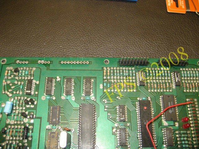
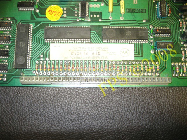
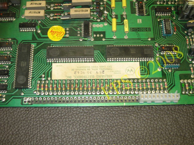
40 pin Inter-board Connector which is situated on the CPU and driver board. On the picture we can see the male connectors 8x5 on the CPU board.
 |
 |
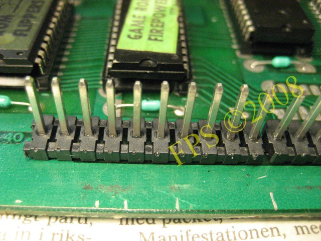
One of the connectors removed - 5x8 pin connector Molex old style.
40 pins Interboard Connectors female connectors on the driver board.
I use the same method to remove this connectors.
 |
 |
The left picture shows new style male connectors and the picture to the right new style female connectors - Molex.
Here we can see the principle for 40 pin Inter-board Connector where the driver board is pushed into the CPU boards connectors.
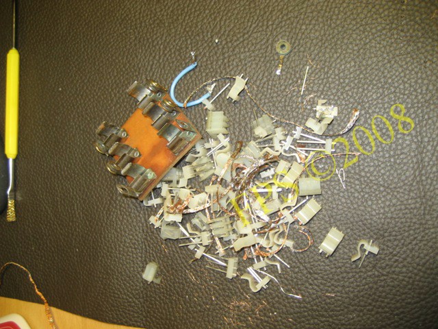
Old battery holder and what is left of the removed connectors.
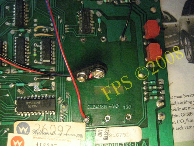
BATTERY HOLDER
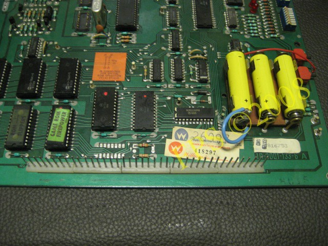
A common problem on this old machines is that they periodically has been stored for a long time with batteries left inside which has start to leak battery acid.
A boards worst enemy is battery acid which is strongly corrosive and hard to remove. It is not always possible to see the battery acid since it diffuse as a invisible film on the components legs and there can come up short cuts and flash-over's. As an example the battery holders terminals is often broken due to corrosion from leaking battery acid.

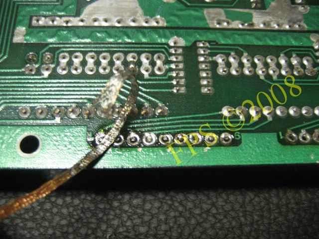
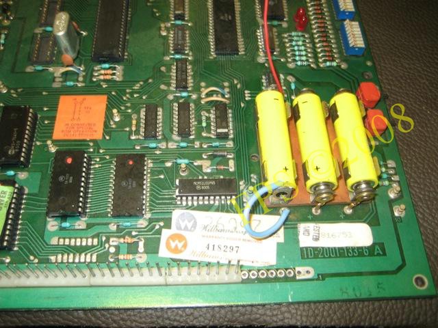
So was the case on mine Williams Firepower 1980 which can be seen on the picture. We can also see how a fix was made with (red/blue) wire to provide the CPU board with battery power. I desoldered the old battery holder and replaced it with a new one.
The ultimate solution is to use a remote battery holder which is placed on the inside of the door in the backbox.
The final solution for me was to replace the new battery holder with a remote battery holder which is placed on the inside of the door in the backbox to guarantee that no battery acid will leak regardless if the batteries is new or old. It can occur that new batteries that is slightly used can havoc and leak battery acid. One red and one black wire is solder to the plus and minus terminal on the CPU board. This exercise is now mandatory on my Pinball's.
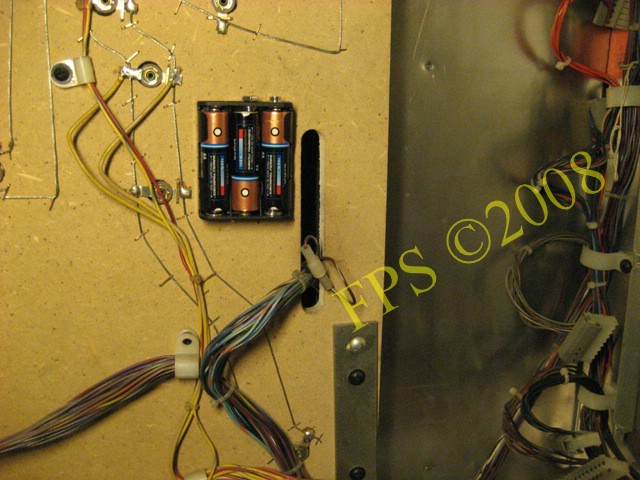
The remote battery holder placed on the inside of the door.
Display problem
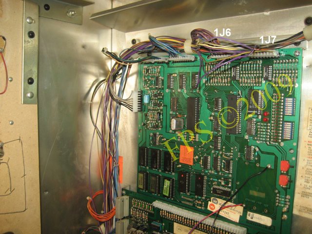
CONNECTORS 1J6 AND 1J7

Something that bother me was the fact that some of the digits on the displays did not worked. Display 1 and 3 showed only four of six digits and display 2 and 4 only three of six digits. The first thing I started with to try to fix the problem was to exchange the connectors 1J6 and 1J7 on the mother board but this did not made any difference. This connectors is for Master display BCD and strobe outputs.
Six digt displays where used on the first system 6 pinballs.
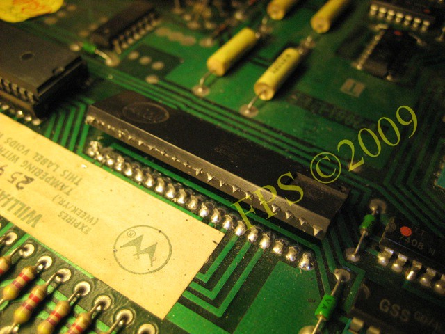
INTEGRATED CIRCUITS - Peripheral Interface Adapter (PIA6821)
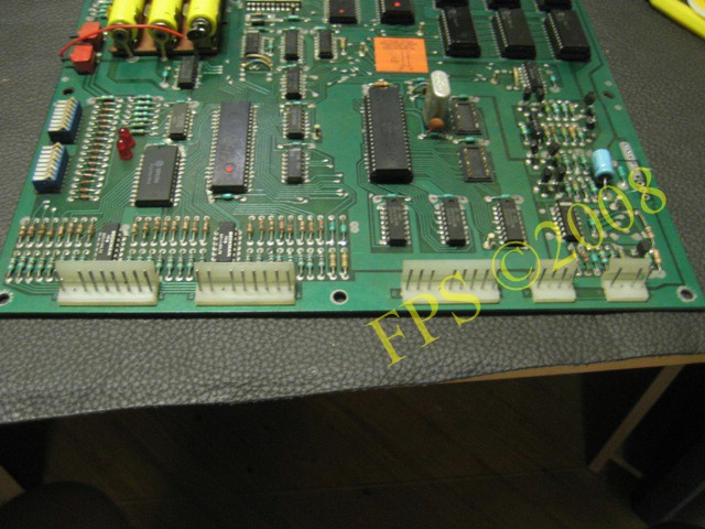
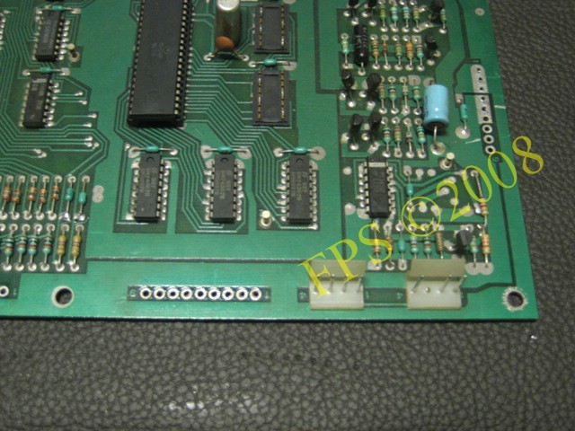
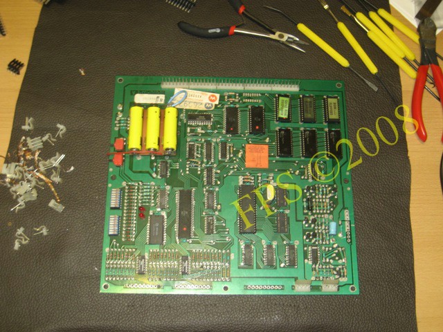
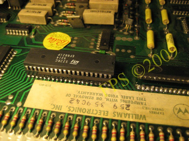
Here is the driver board - I exchanged the solenoid PIA6821 IC5 and display PIA6821 IC18 on CPU board to secure that this IC not is the cause to the display problem. Also to now if future problem should occur it is not related to this IC´s which is almost 30 years old.
First I cut the IC legs with a long nose pliers.

Then I cut the IC legs on the other side.
Then I desoldered the tin on the backside of the board to uncover the legs - here I use a tin sucker. After that I heat the legs with the solder iron and pull out the legs with a pliers.
Finally I remove the last tin with a solder wick on the backside of the board.
The principe is the same if a IC socket shall be removed.
 |
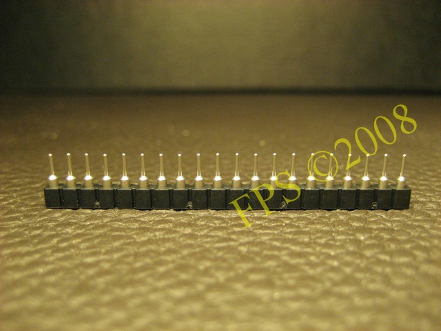 |
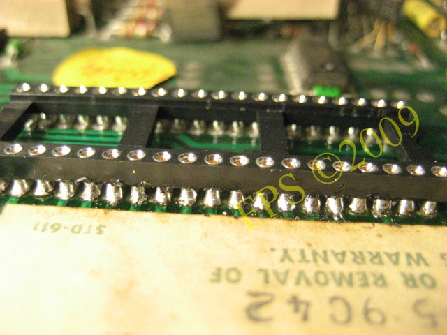
A new IC socket is soldered. The best type of IC Socket is a 20 Pin Single In Line which can be cut in feasible number of legs, right picture.
 |
 |
In the picture to the right all legs is soldered. Afterwards I solder the legs underneath the socket to assure contact between both side of the board. I use a multimeter to continuity check all trace from the socket legs to assure that there is no break.
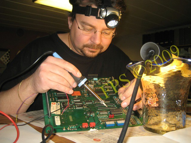
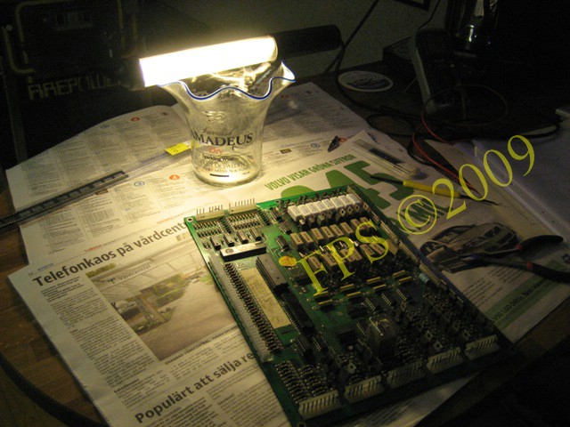
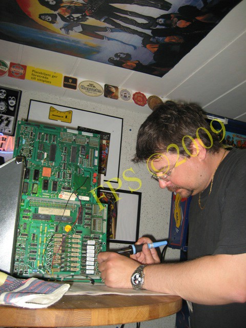
Ohhh - Here I'm busy with soldering!
 |
 |
Now is the new socket installed and no break is found.
Then PIA6821 IC is installed in the socket.
It looks like IC5 have been exposed for battery acid but I'm not sure if there is any problem with the IC.
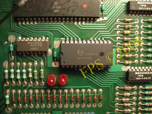
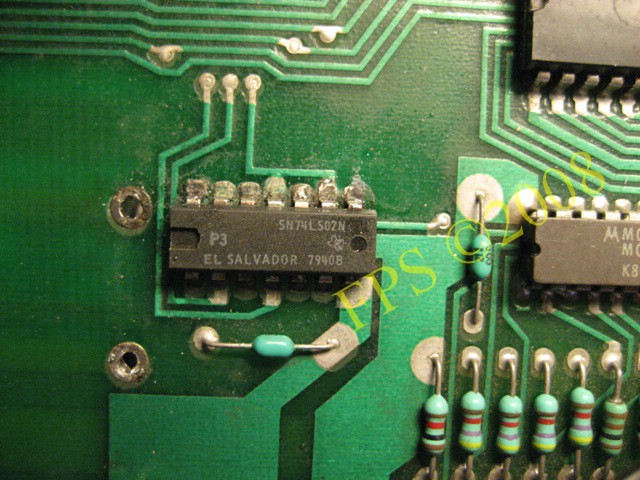
Exchange of IC6 #74154 - 4 to 16 decoder.
CONNECTORS ON PCB BOARD

Over time the tin can be old and miss conductivity and also cracks can occur with result in bad connection. Therefore it is a good idea to resold the legs on the connectors or even replace them with new type of Molex connectors that have square pins.
TRANSISTORS - LAMP MATRIX
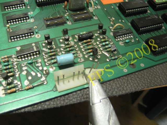
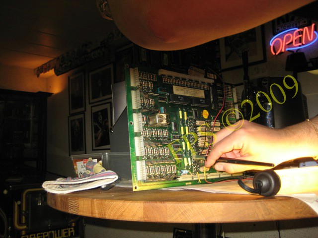
Some of the lamps on the playfield did not worked so I Started to check if any transistor on the driver board has failed. With a Multimeter I continuity measure all transistor by following the below method,
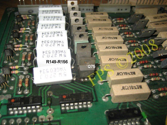
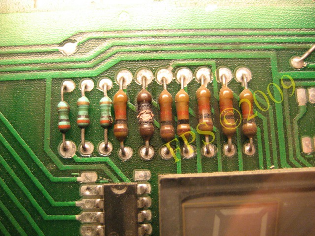
If measurements of transistors show that it is open or not open in both measurements, collector and emitter with base as common, then we can assume that the transistor is faulty and it need to be replaced. In my case it showed that the transistor (Q75) TIP42 for lamp column was faulty, which is the most forward transistor in the picture.
I also exchanged the 27 ohms 5W resistors for the lamp matrix R149-R156 on the driver board to prevent overheating, since the original often get overheated with age. The resistors shall be placed with a distance of 2-3 mm to the driver boards surface to aloud air to flow around them to reduce the heat.
STILL PROBLEM WITH THE LAMP MATRIX
Some of the CPU controlled lamps on the playfield and in the backbox lights up all the time and do not turn on and off in attract mode so I started to control the diodes 1N4001 mounted on each lamp socket on concerned lamps. The lamp diodes where not broken or open, then I started to identify which transistors on the Driver board that correlate to respective lamp. There are transistors for the lamp Row and Column.
Firepower lamp matrix
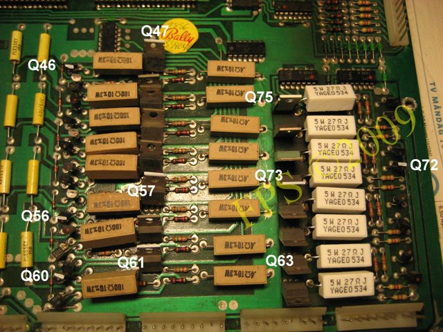
In the below matrix is the transistors that I replaced to fix the CPU controlled lamps.
| ROW 6 | Q57 | 2N6122=TIP31C |
| Q56 | 2N6427 | |
| ROW 7 | Q61 | 2N6122=TIP31C |
| Q60 | 2N6427 | |
| ROW 1 | Q47 | 2N6122=TIP31C |
| Q46 | 2N6427 | |
| STROBE 6 | Q73 | TIP42 |
| Q72 | 2N6427 | |
| STROBE 7 | Q75 | TIP42 |
| STROBE 1 | Q73 | TIP42 |
| Q72 | 2N6427 |
 |
 |
I use two Magazine collectors to put the circuits boards to facilitate the removal of concerned transistors, I heat on the solder points on the back of the circuits board and pull out the transistor very gently from the circuit board. I use a glove since the transistor becomes very hot.
When to suck away the excess solder tin I move one of the magazine holders, so that circuit boards can be put down on the table.
After the transistor is removed, all solder tin leftovers is brushed off with a paint brush.
I am soldering a new replacement transistor to the Driver board.
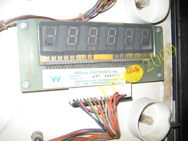
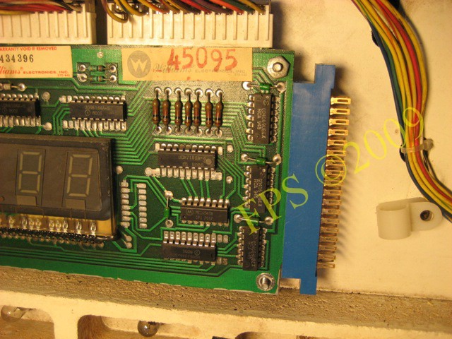
MASTER DISPLAY BOARD
After some play on the machine a segment on all digits where lost. When I inspect the Master display board I found a burnt resistor. I replace it with a new one and the problem was solved.
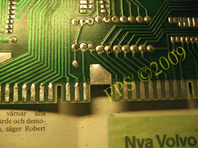
Wear on the tinplates on the Master display board will appear after several reconnections of connectors. I resold extra tin on this plates to increase the continuity between board and the connectors.
REPLACE WIRES BETWEEN CPU AND MASTER DISPLAY BOARD
|
 |
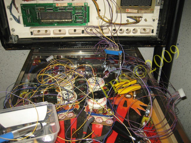
I replace the cables that goes from 1J6 and 1J7 to Master display board since it is still a digit that does not appear in displays for player 1 and 3. When I flex the contacts and the cables for1J6 and 1J7 digits in the displays will disappear and start to blink.
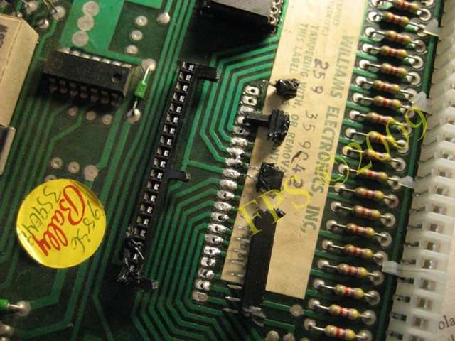
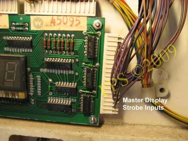
The contact for the Master Display Strobe Inputs, I will replace with a Edge connector 2 x 18 pin (JAMMA), see picture.

For 1J6 and 1J7 I use traditional Crimp Contact Female for 0.156 in. Molex Connectors which is attached to the end of the wires with a Molex crimp pliers and Molex 9-Pin Female Housing .156" connector with Ramp.
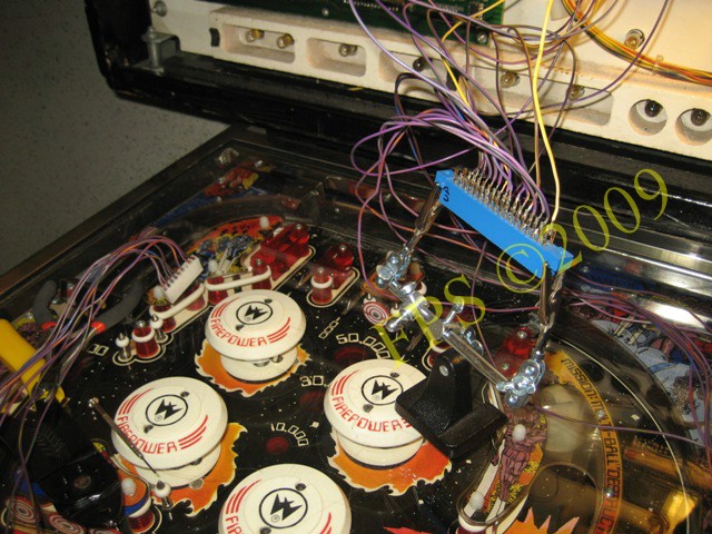
I use a solder stand to hold the JAMMA connector when I solder all the wires to it. To solder the wires feels more safe than using traditional crimp contacts and a female housing.
There are some wires to keep track of when soldering them to the JAMMA connector.
FINALLY, FINALLY DISPLAY PROBLEM IS GONE
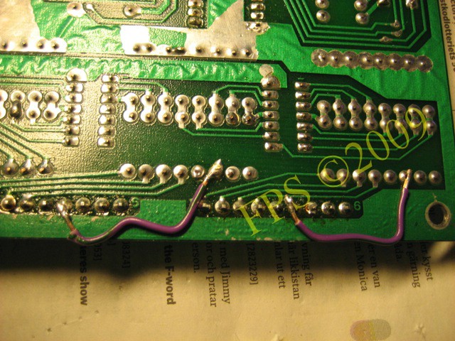
After the change of cables between 1J6/1J7 and Master Display Strobe Input connectors it was still a little problem with the numbers in the displays. I did a continuity measurement between strobe outputs resistors R71-R86 and contacts 1J6/1J7. Between R73 and 1J7, it was almost no contact and between R81 and 1J6 there was poor contact. To solve this problem I made a bridge on the back of the circuit board with two cables between the contact points.
When I tested with the card installed in the pinball again was the problem with the displays gone. All displays showed all 6 digits without any remarks.
Pleasure and Pinball
© FPS. All right reserved. |
Page Last updated:
2009-03-24 |